1971 Laverda 750SF Bottom End Assembly
This page covers the first session of reassembly of my 1971 Laverda 750SF engine, putting the cases together and installing the clutch and primary chain. The hands you see in the photos are mostly those of Scott Potter, a very experienced Laverda restorer.
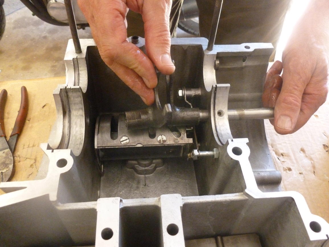
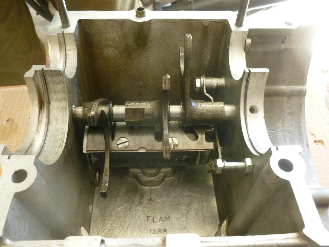
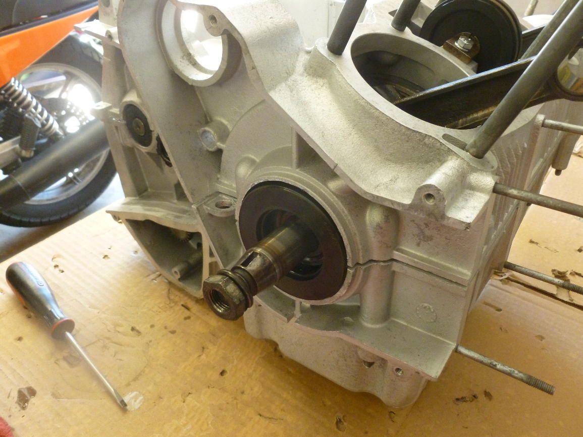
I missed the first few steps of installing the shift selector drum. Looking from the front of the engine. The keyed shaft comes in from the right side of the engine (left in the photo) and is secured by the nut (note the washer) on the far side of the drum. The end of the shaft floats in a hole in the left side of the lower case.
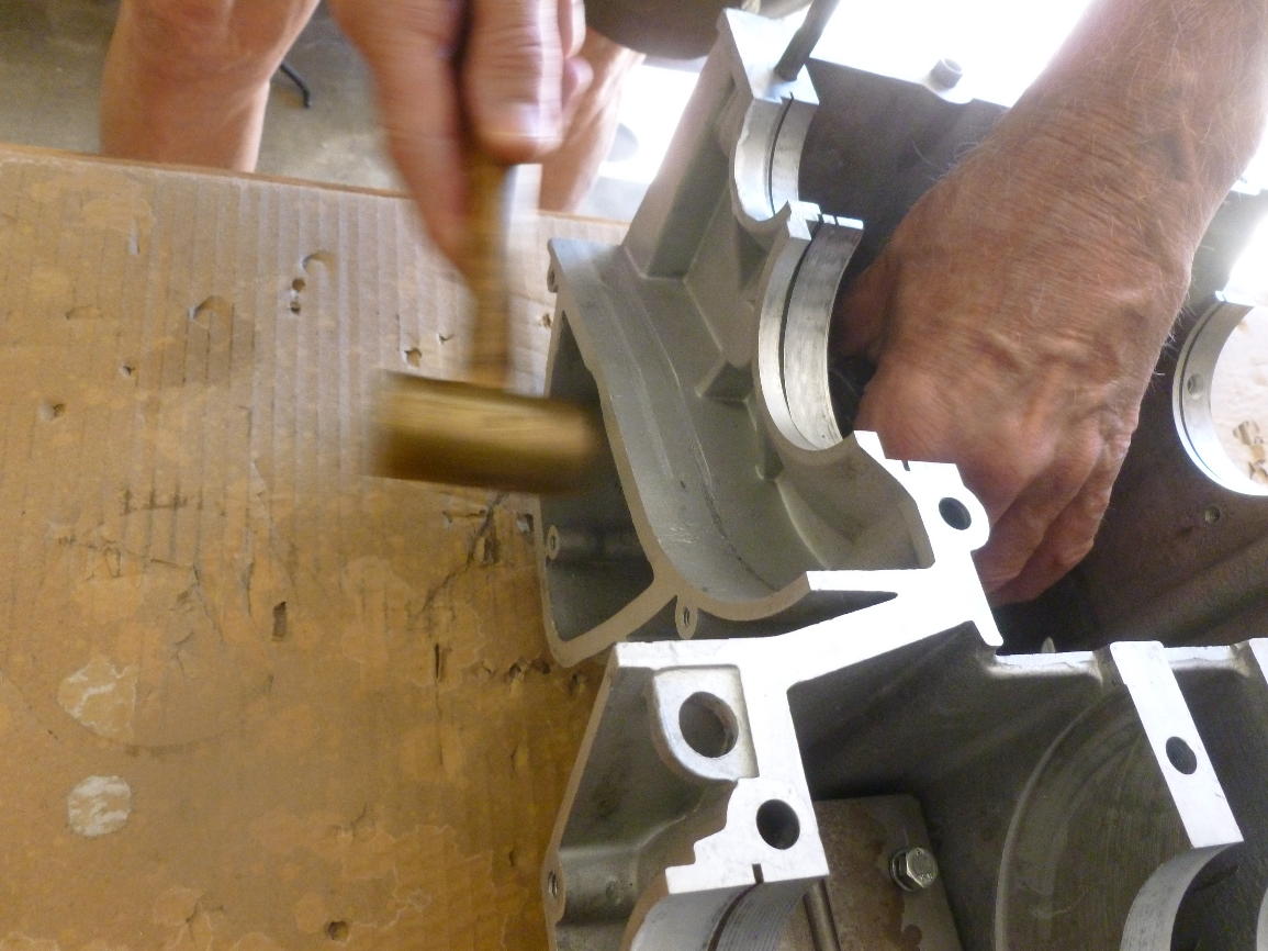
The shift drum shaft takes a little persuasion to be pushed home.
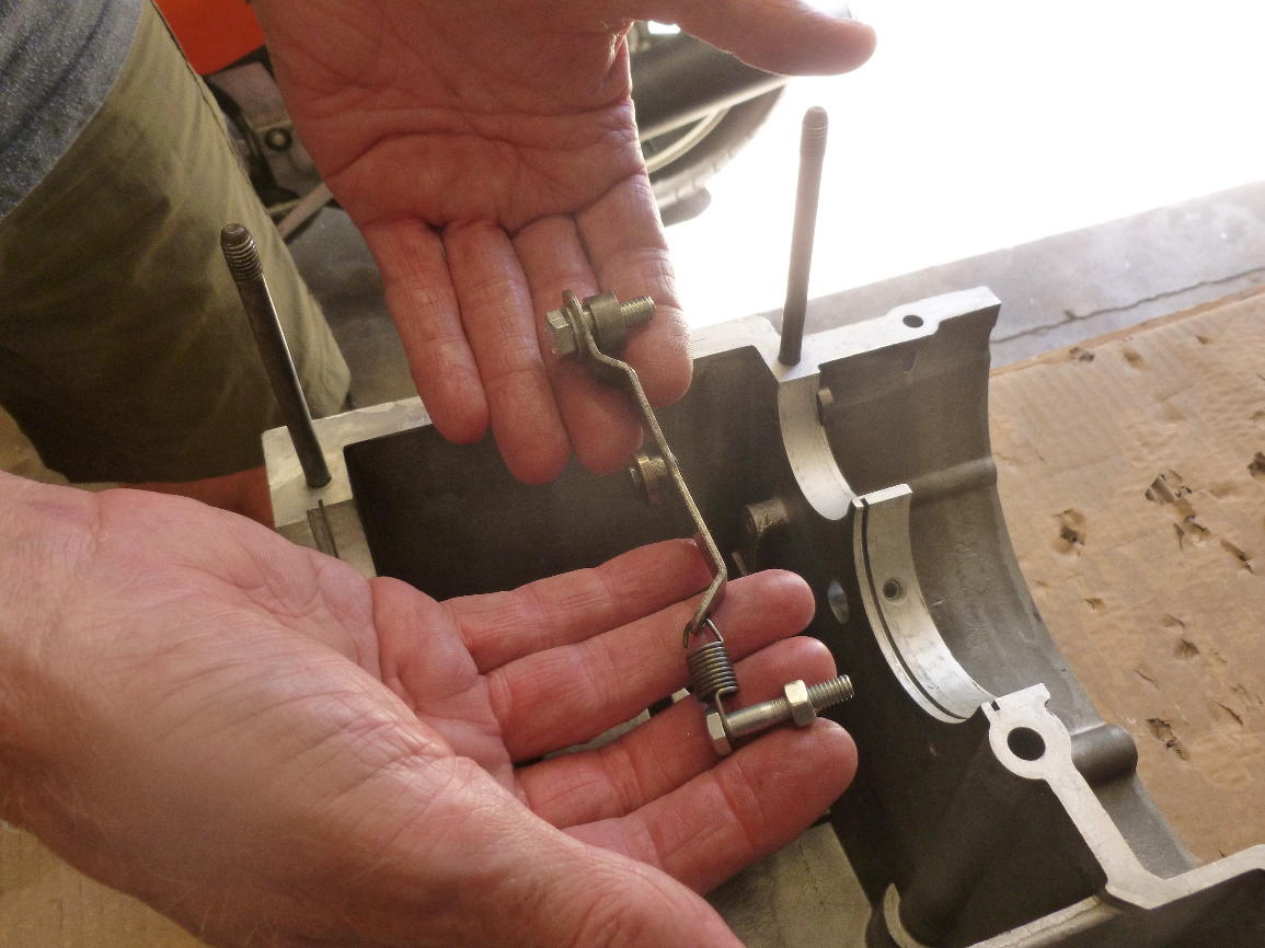
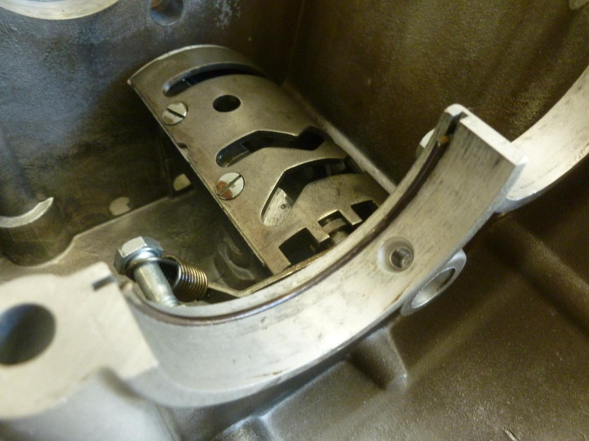
This is the detent mechanism that locates the shift drum for each gear. The spring should always be replaced if the cases are split.
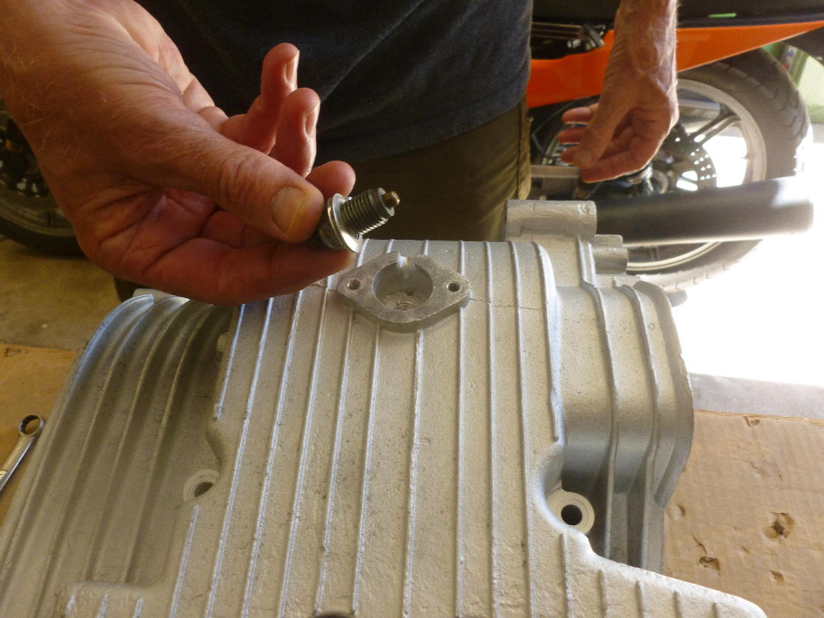
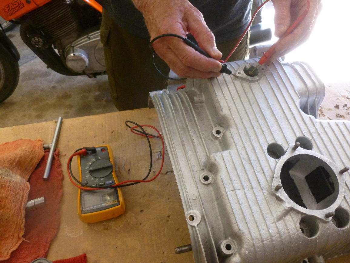
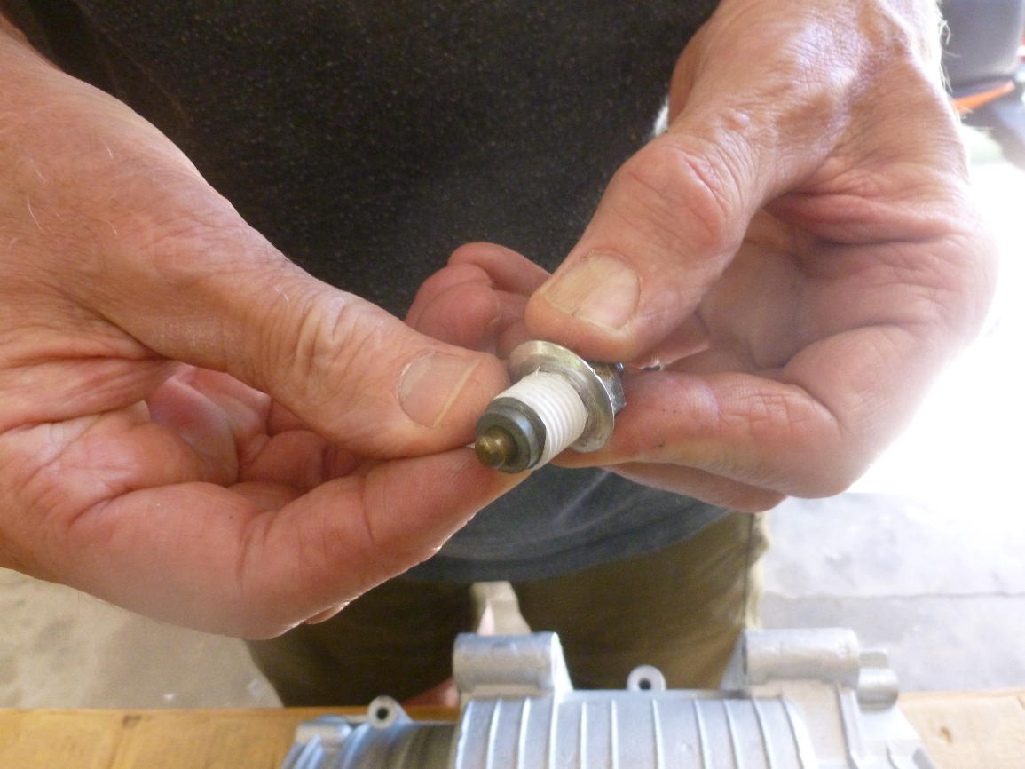
After the shift drum is installed, install the neutral switch. When the gearbox is in neutral it grounds to the case, so it’s easily checked with a volt-ohmmeter. The clearance is adjusted by adding or removing shims. Wrapping the threads with teflon tape helps prevent leaks, but be sure none of the tape gets inside the engine. Old switches sometimes leak through the plastic, but you can fix it (usually) by cleaning it carefully and smearing around the metal-plastic joint with RTV sealant.
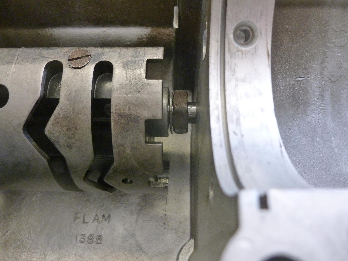
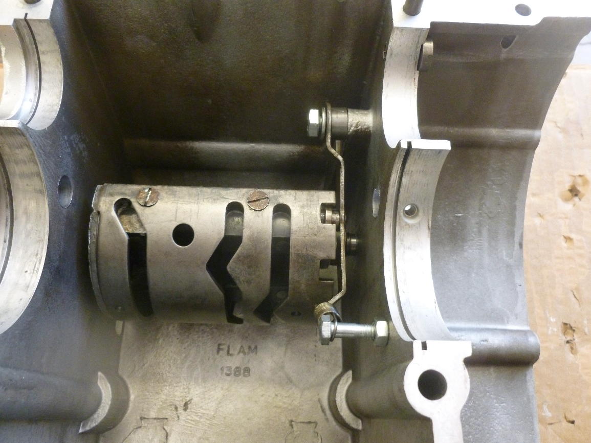
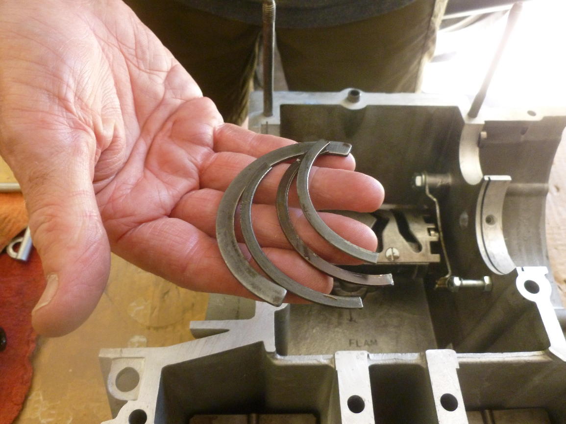
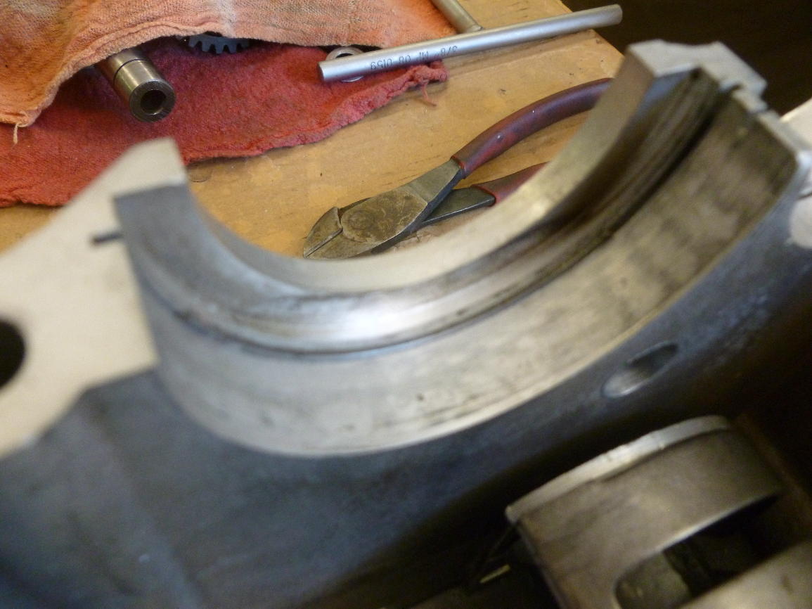
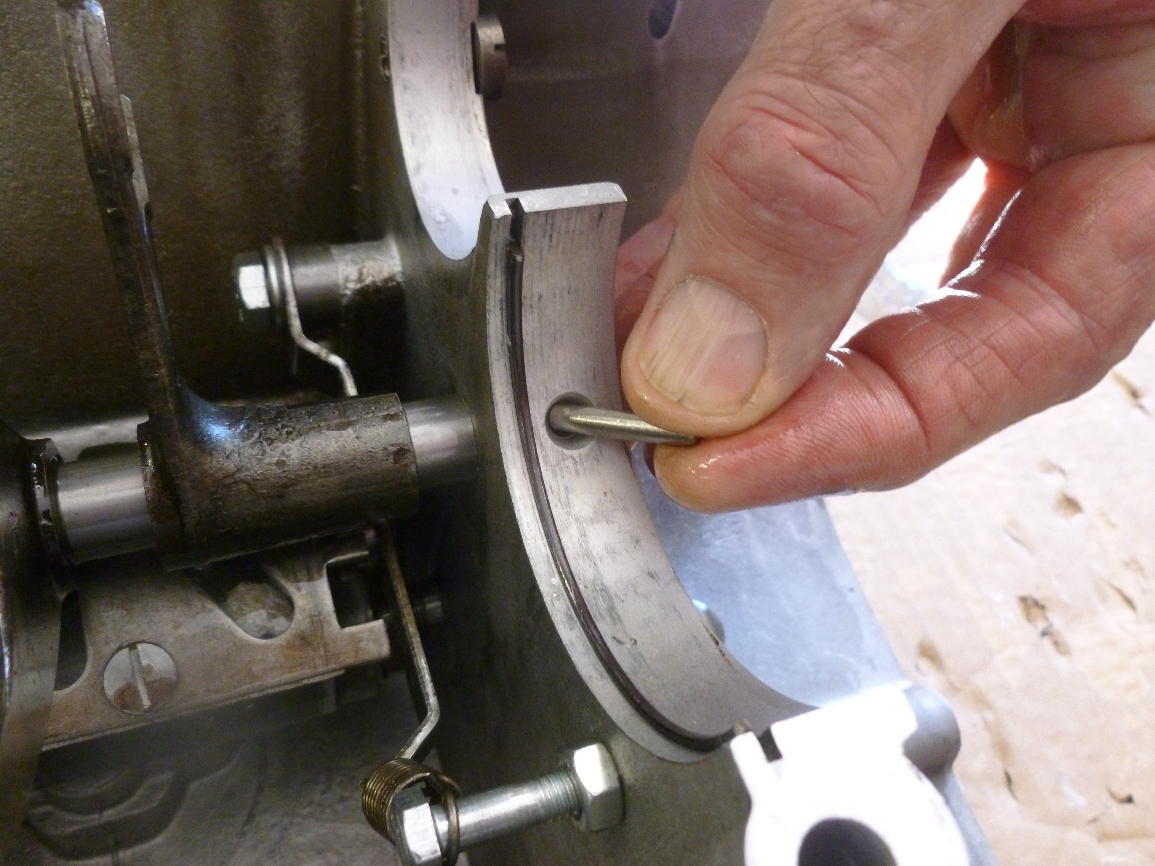
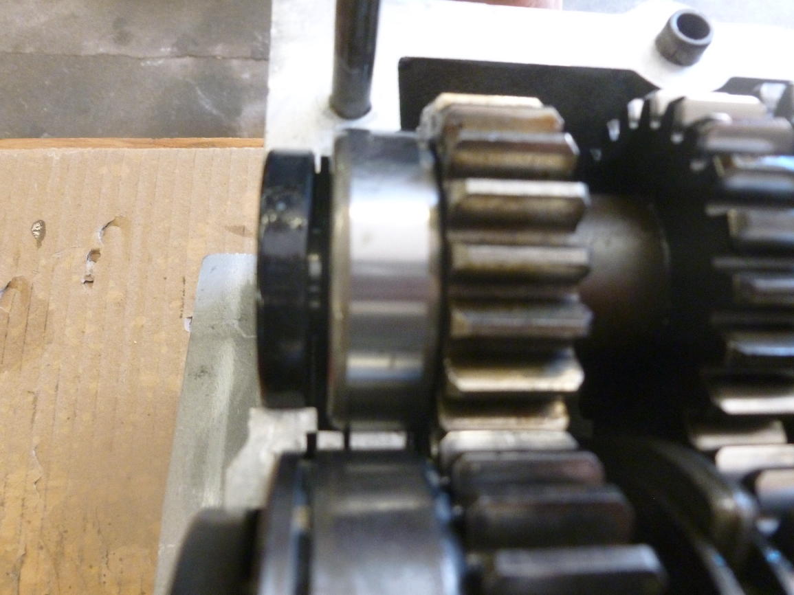
Partial rings are used for locating the two outer main bearings, the two gearbox mainshaft bearings and the right side bearing of the layshaft (the left side is located by a special brass screw). They are all different radii.
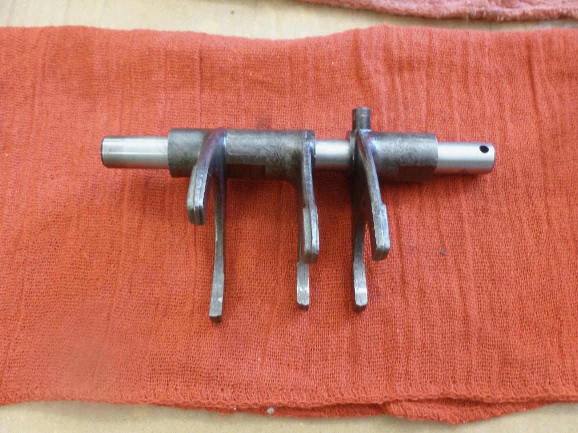
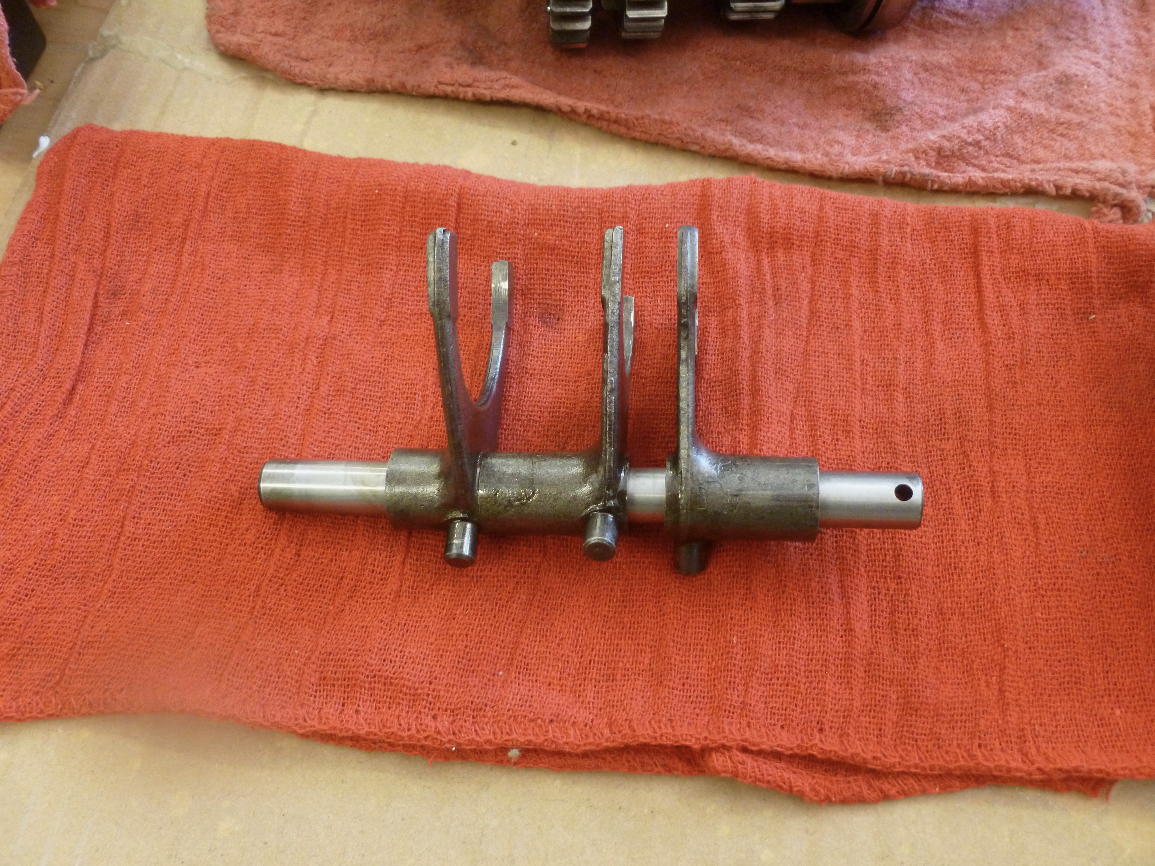
The shift fork assembly. The end of the shaft with the hole goes on the left, where it is locked in by a pin under the mainshaft bearing. The left-most fork (pin side) engages the layshaft (to the rear), the other two engage the mainshaft.
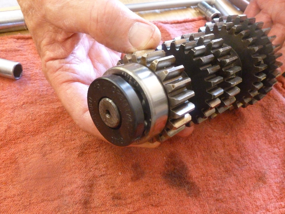
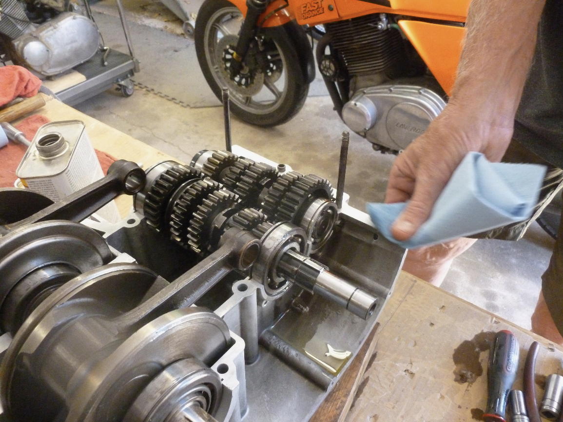
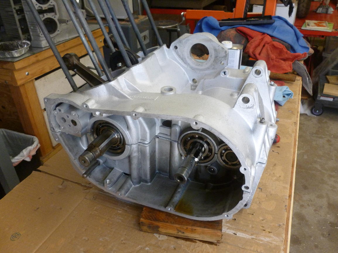
Now it’s time to install the gear clusters. The seal has been installed on the right side bearing of the mainshaft. The seal is not right up against the bearing, the beveled edges protrude beyond the case. Everything is well-oiled and the bearings are tapped down to be sure they are seated.
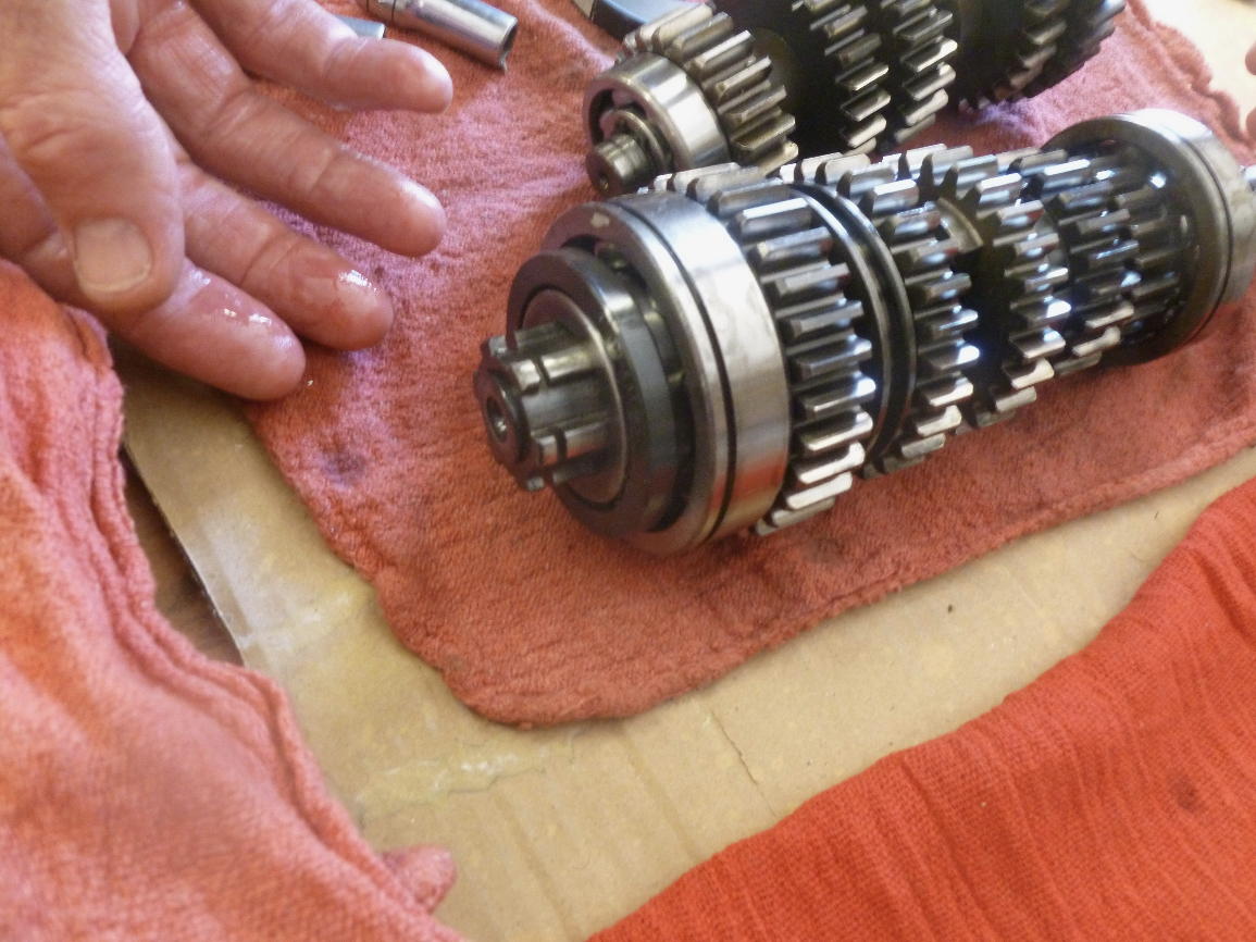
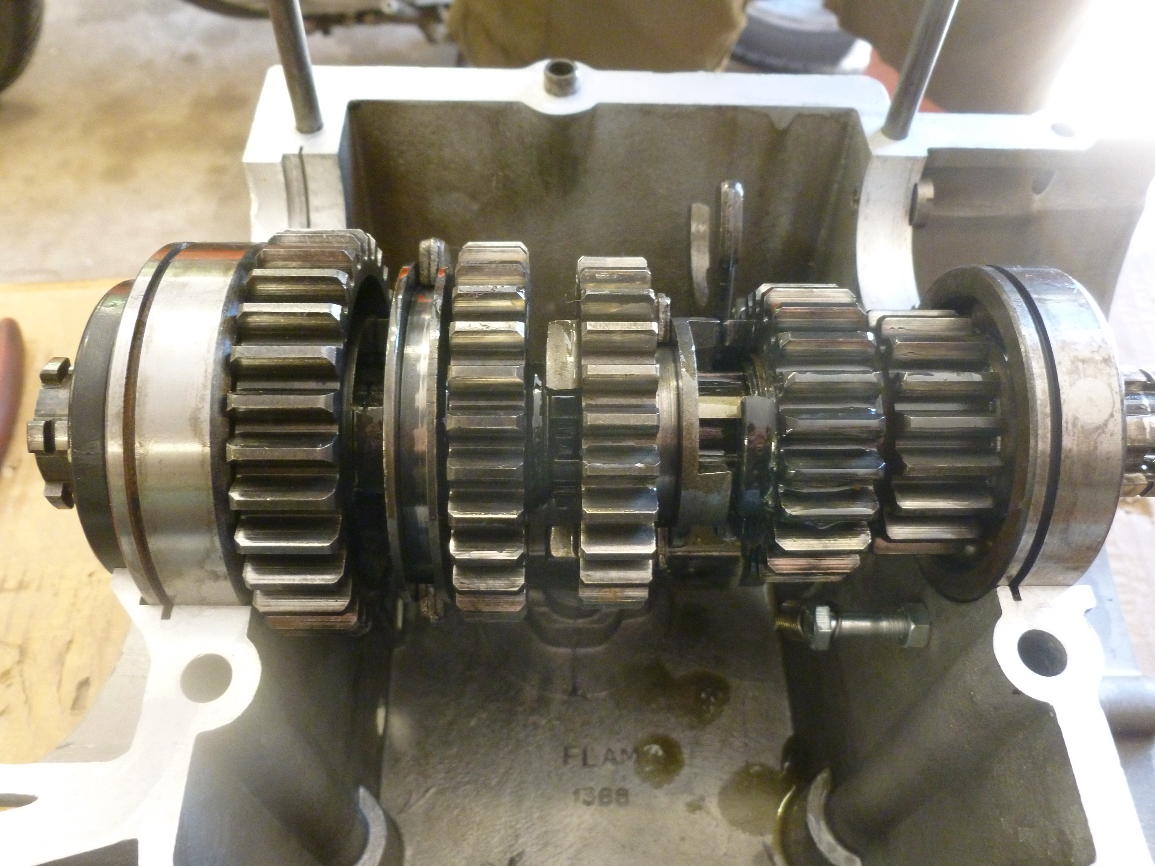
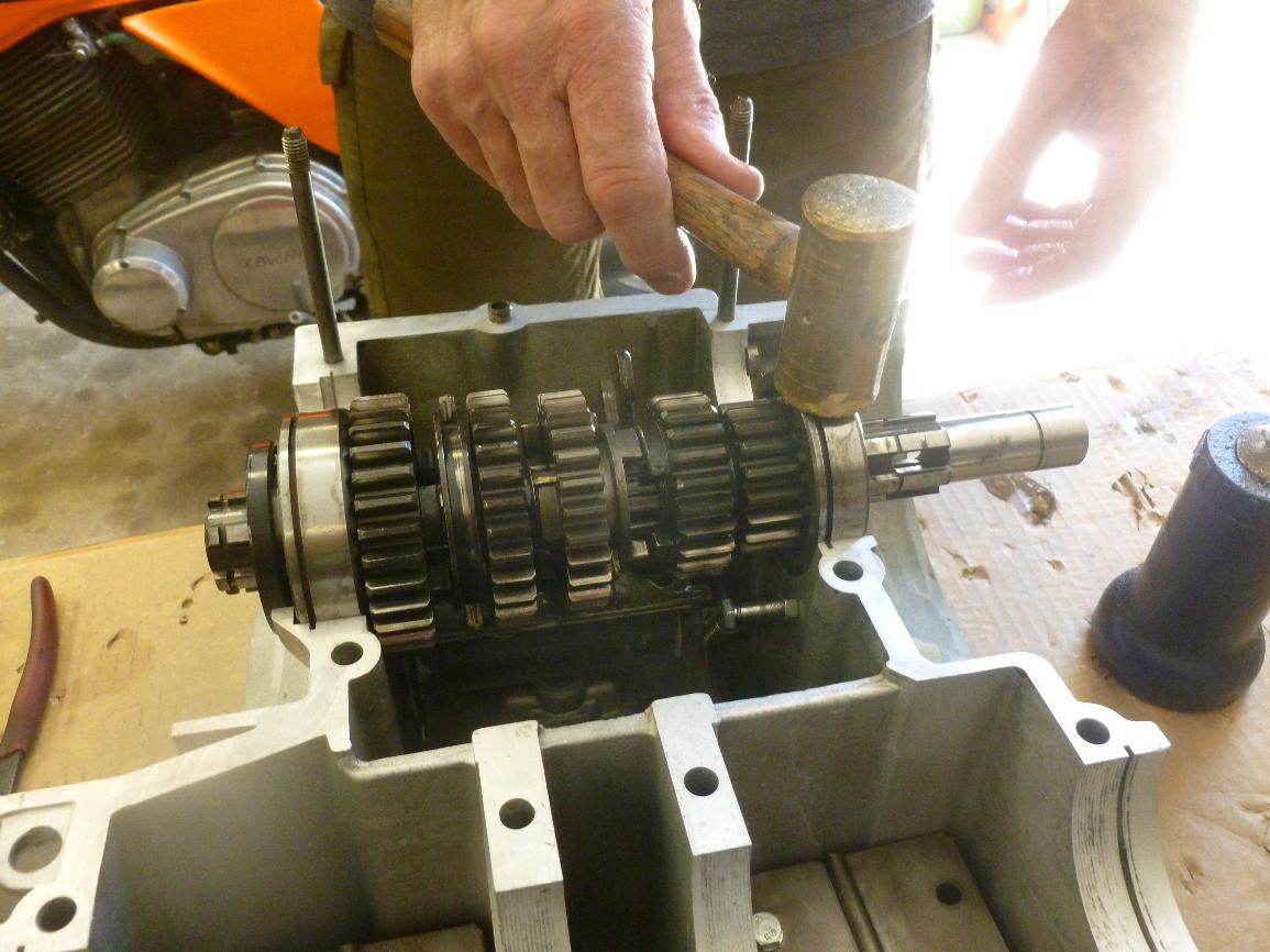
Now the layshaft gear cluster is installed, with its oil seal.
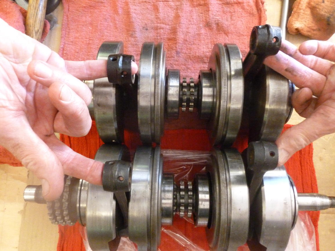
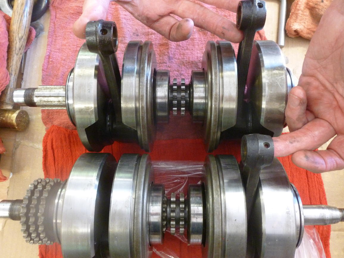
The next two photos show the difference between the crankshaft of a 750GT (bottom) and my 750SF (top). The counterweights of the GT crankshaft are thicker and the crankshaft is heavier. Scott had used the GT crankshaft in the bottom end of the SF2 cases he built.
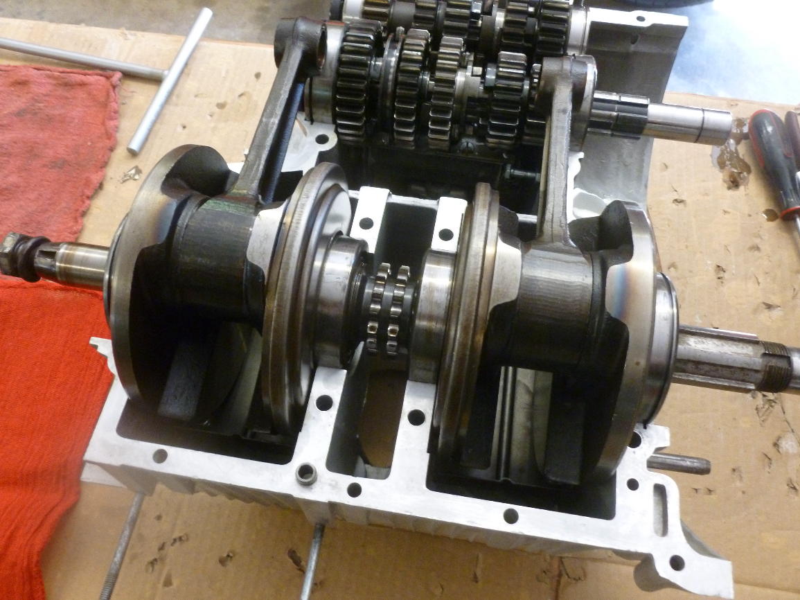
The crankshaft installed.
The oil seal protrudes a little. It’ll be clamped tightly by the cases.
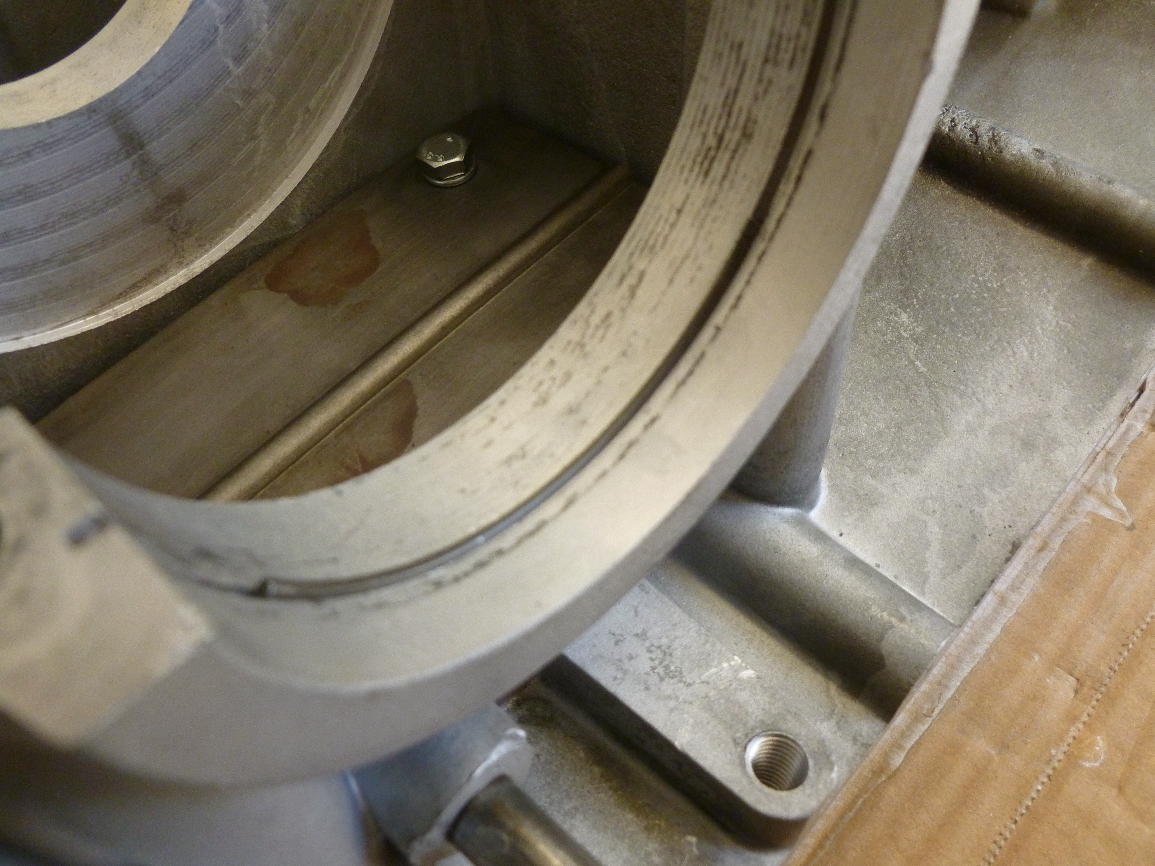
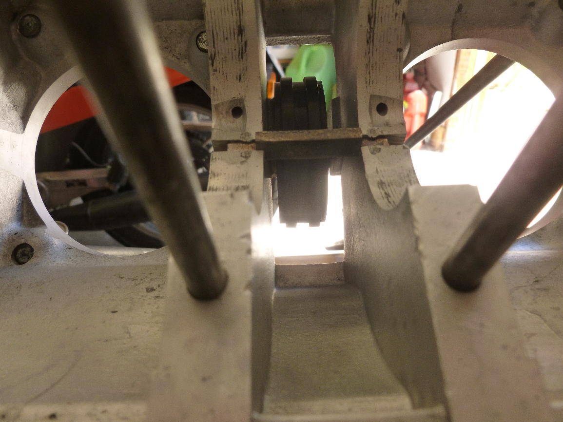
The prupose of this little block in the upper case is to control the spacing between the inner two main bearings. It is peened into the case so it can’t fall out but it is not tight.
Before joining the case halves, the mating surfaces are cleaned carefully with acetone.
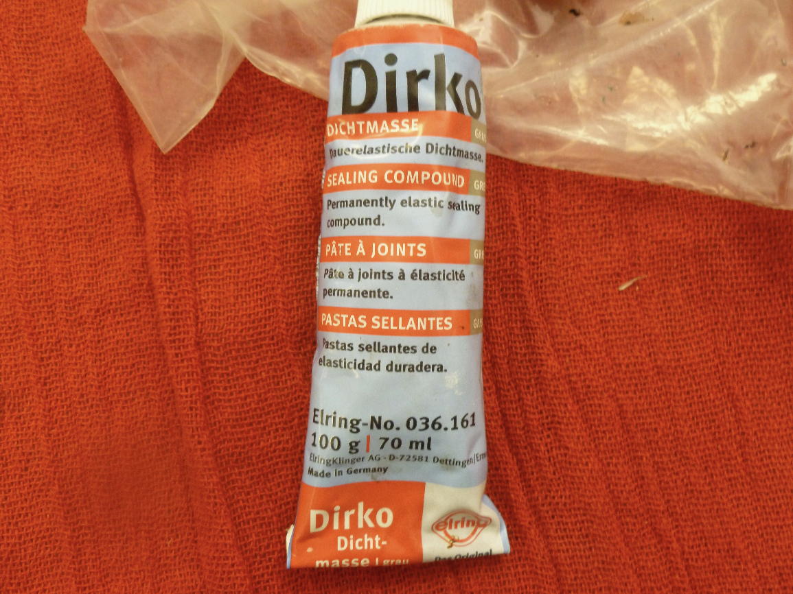
I used a German sealant (non-hardening) called Dirko that was highly recommended by Wolfgang Haerter, the main supplier of Laverda parts for North America. He told me it was originally developed to solve a troublesome oil weep on the cylinder heads of Honda 750s. Dirko can stop such leaks even if applied externally.
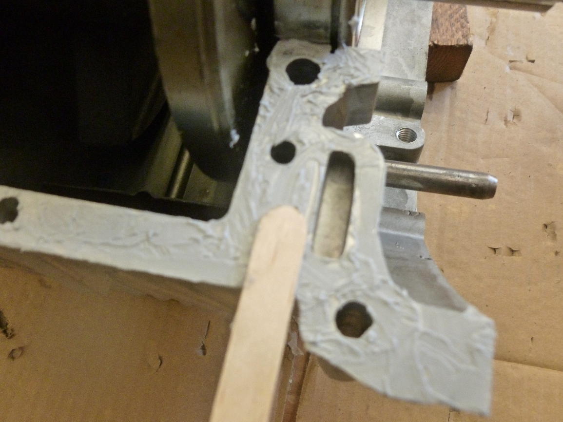
Popsicle sticks make a good applicator for the sealant. The sealant is mainly applied to the bottom case, but in a few crevices it’s easier to put it on the corresponding part of the top case.
The cases are joined, but not fully home yet.
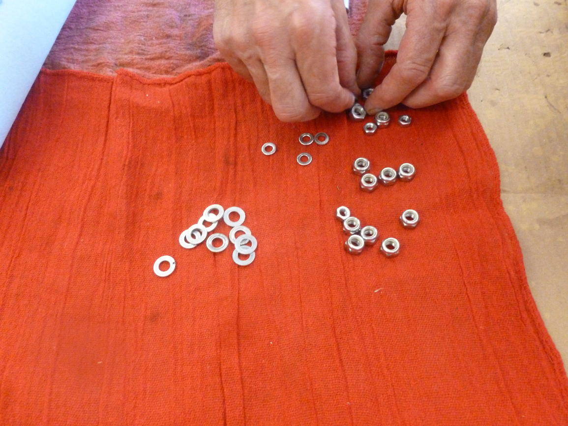
The cases are clamped by two sizes of nuts on studs, 6 x 1.0 mm and 8 x 1.25 mm. I ran new dies over all the stud threads before beginning the assembly and fresh nyloc nuts over steel flat washers were used in most cases.
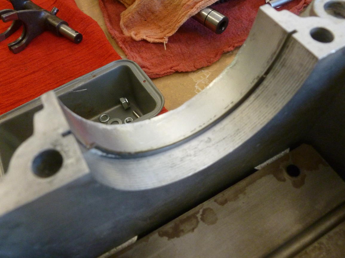
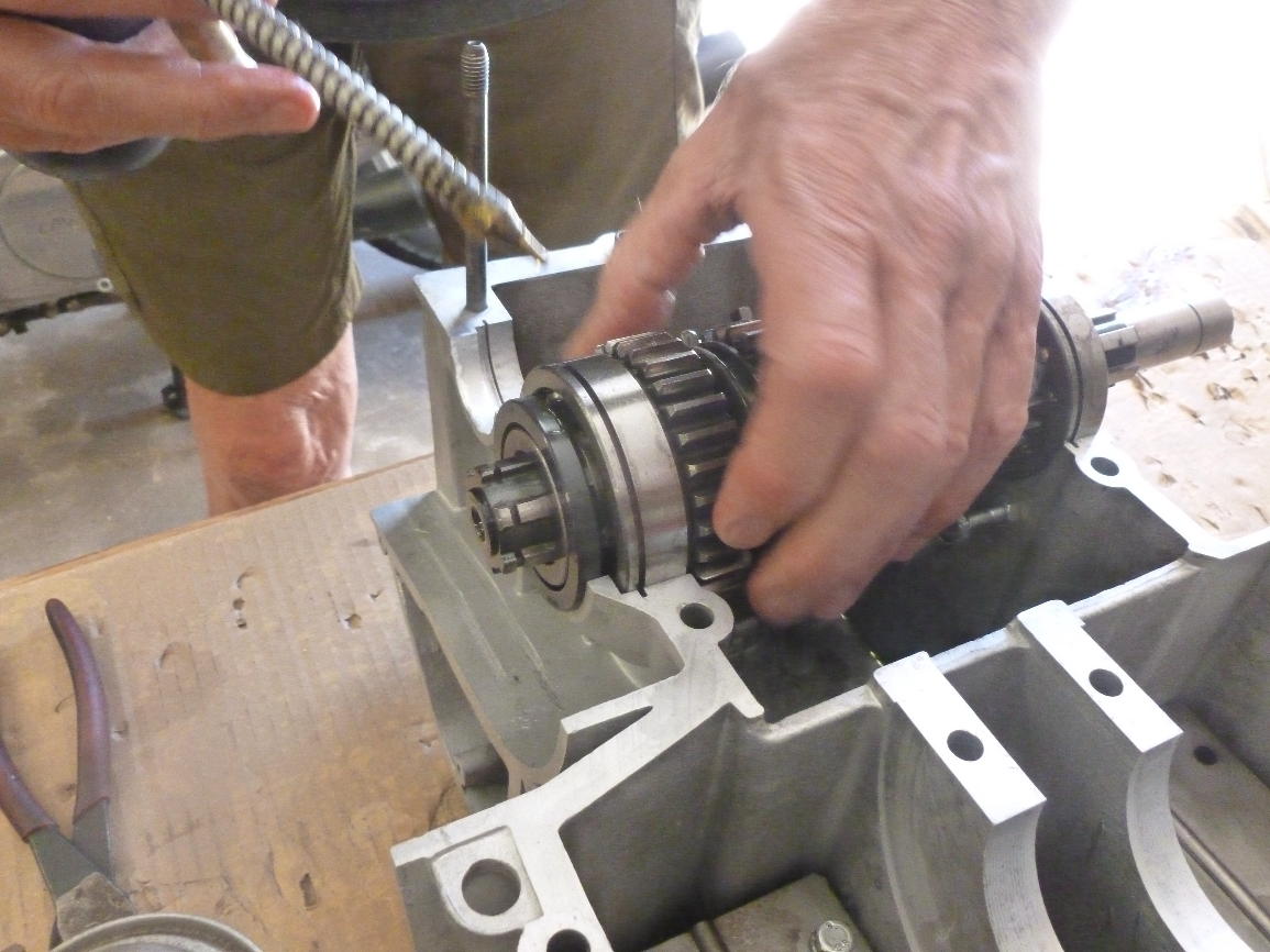
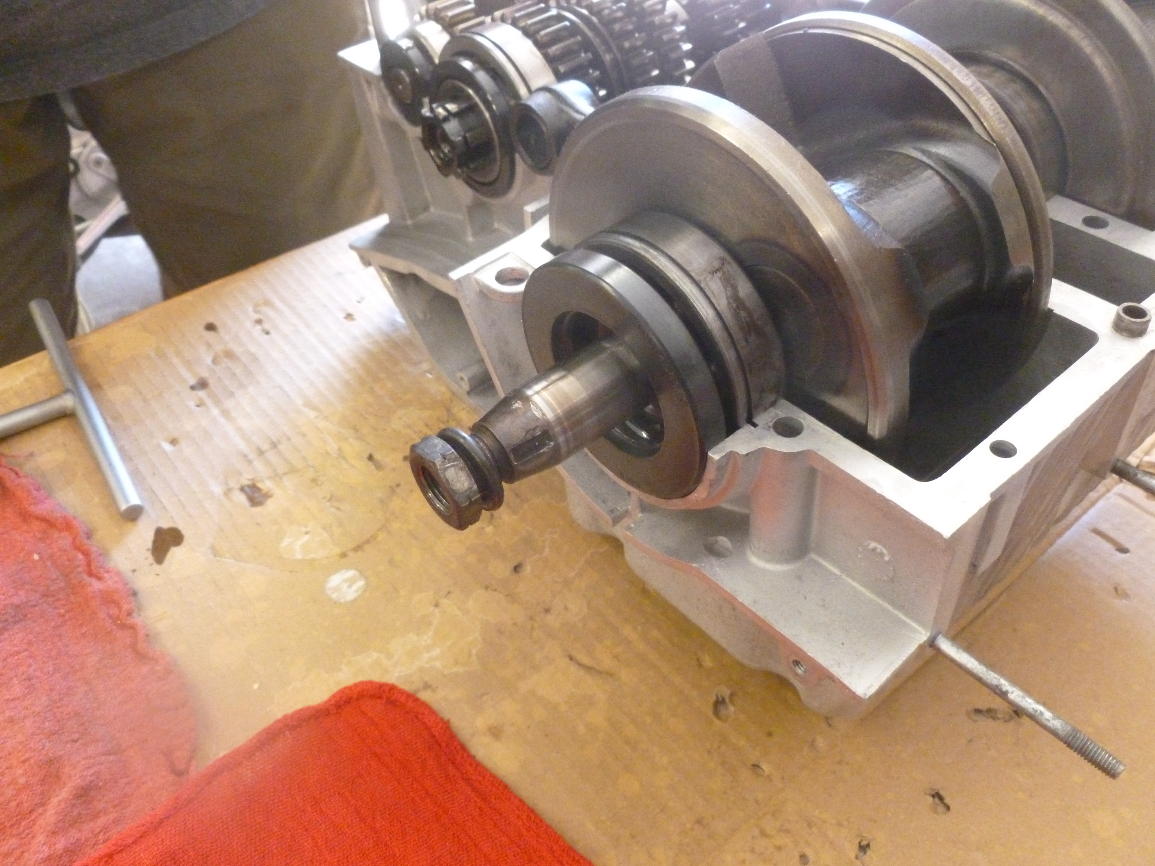
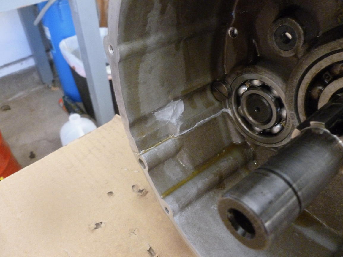
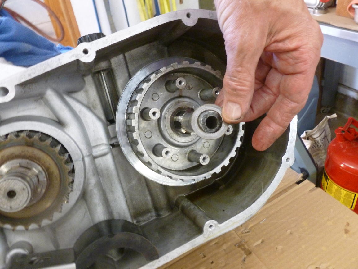
At the rear of the primary (left) side one of the 6mm studs breaks through into the space, posing be a major leak potential. The engine is upside down in the next three photos. In the next one you have a good look at the special screw that retains the primary-side bearing on the gearbox layshaft.
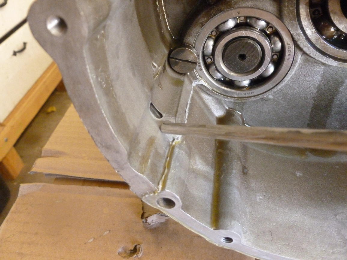
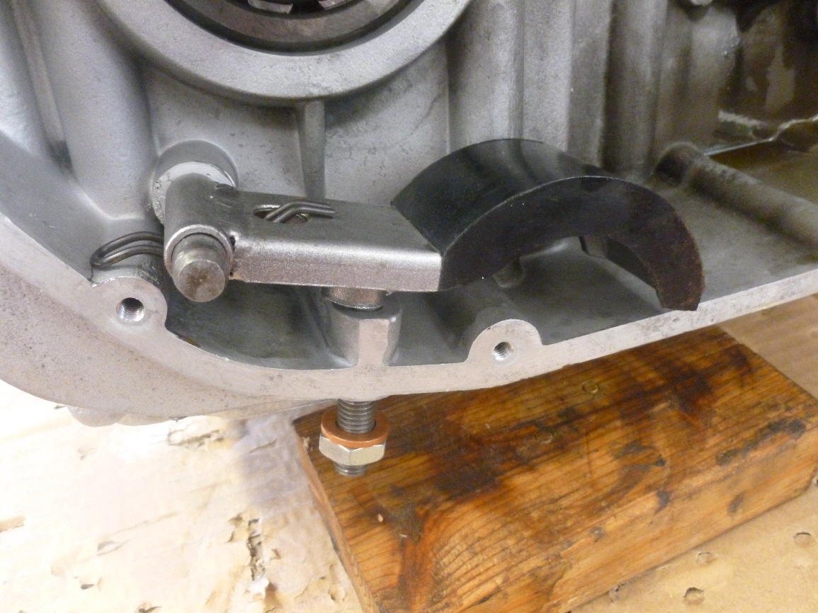
That is why this stud gets a dome nut over a copper washer.
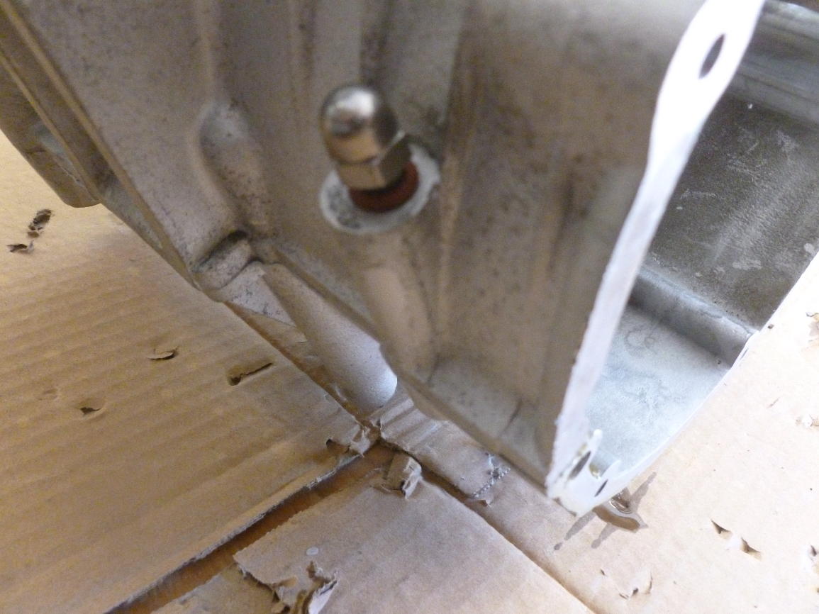
It doesn’t hurt to fill up the stud cavity with sealant, either.
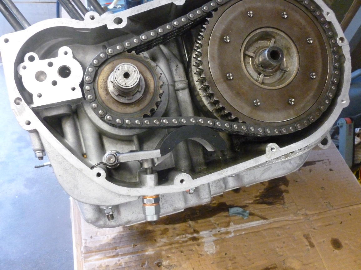
I replaced the primary chain tensioner with an improved, later model.
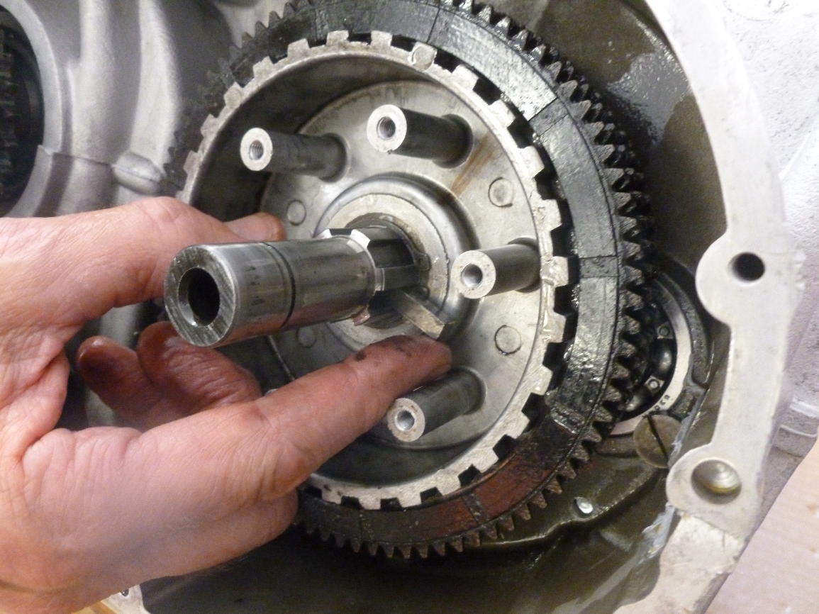
Starting installation of the clutch and primary drive. The front sprocket slides easily on its splines.
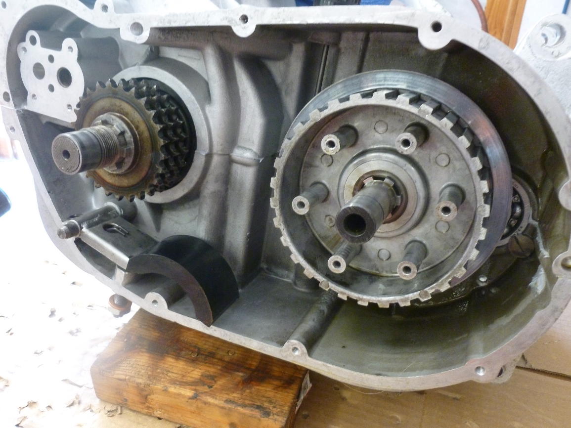
The inner clutch plate is held in place by a circlip (not yet installed).
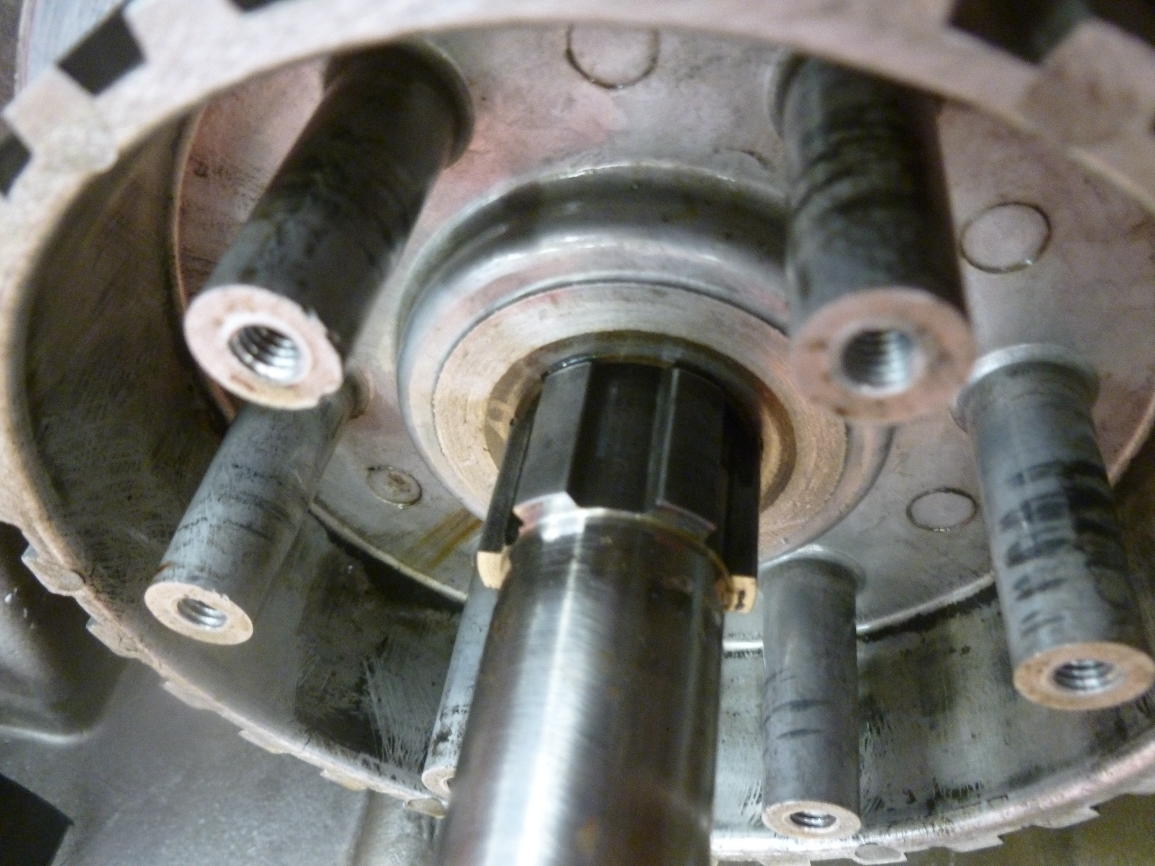
Alignment of the front and rear sprockets is critical. Push the outer clutch hub onto the shaft and lay up a straightedge from the side of the outer teeth.
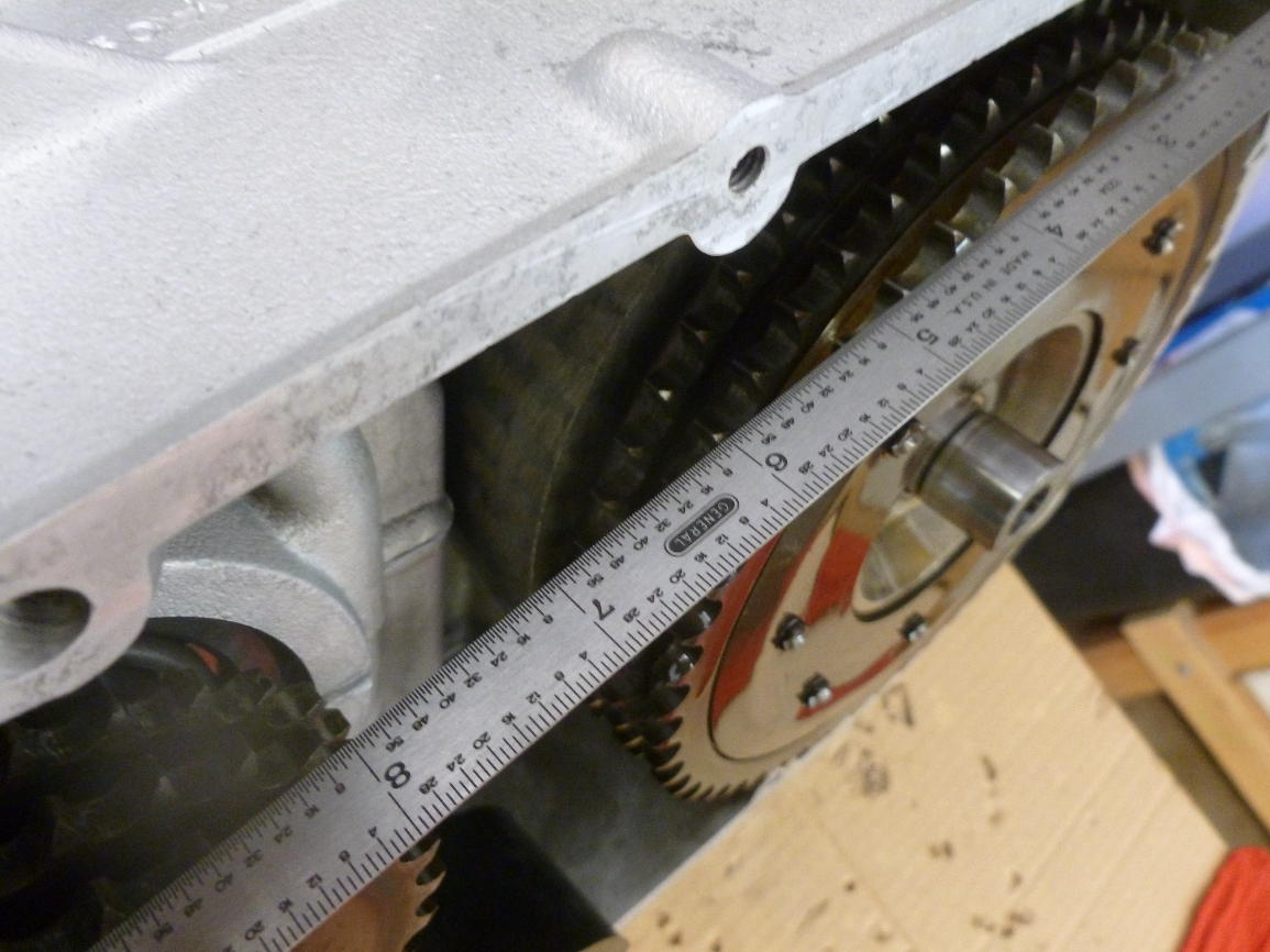
Several sizes of shim are available to adjust the alignment.
This bar is the piece that is pushed by the clutch rod to lift the pressure plate off the stack of clutch plates and disengage the clutch.
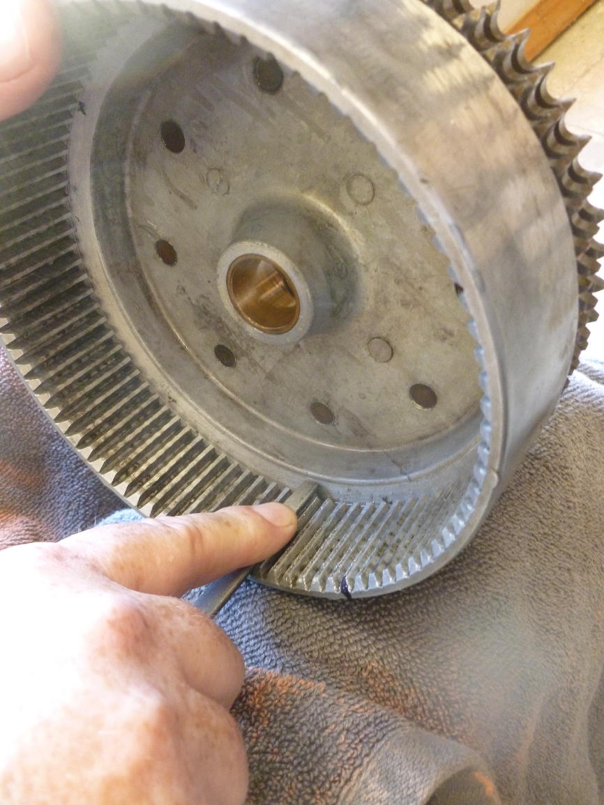
The clutch hub is aluminum alloy and the teeth on the clutch plates are steel, so the grooves in the hub get beat up over time. This makes for notchy clutch action and it makes it harder to install the outer hub over the clutch pack. A tool to address this problem can be easily made. Find a triangular file of a size that fits the grooves pretty closely, cut off the tapered tip of the file (about an inch on mine) and grind off one corner of the file for several inches. This lets the file sit down in the grooves of the hub without bottoming out. Then grab a beer and a comfy chair, put a towel in your lap and work your way around the ten thousand or so grooves, giving each one the same number of strokes (I did 5). Mark with a felt tip pen to know where you started.
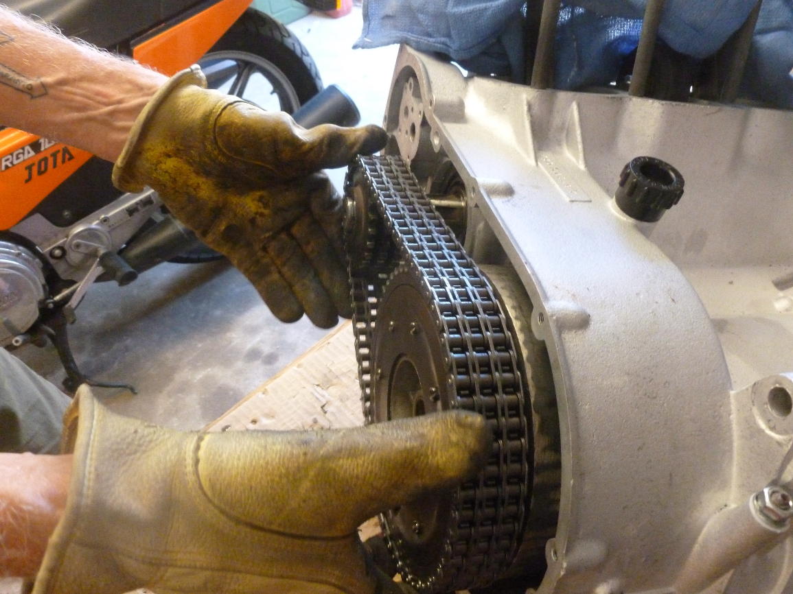
Next, install the clutch pack, place the pressure plate over them and very gently hold in place with one of the six spring/screw combos. Now the Big Fun happens, which is not documented photographically here because we were too busy cursing. In the Green Book (the Bible of Laverda owners) it’s described in one off-hand sentence: you gently push the outer hub over the plates, wiggling things so that the teeth go into the grooves. Maybe if you have all brand new parts it goes like this, but if you’re reassembling with used parts be prepared for something much more challenging. Taking the time to visually inspect and adjust the alignment of the teeth is absolutely necessary. Scott has a cut-away clutch drum made from a trashed one, which gives your fingers room to adjust things as the hub goes in, but we did not have that on hand. After a great deal of travail we installed the clutch throwout bits, put a couple retaining screws in the pressure plate and actually disengaged the clutch while sliding the hub home. This seemed to help, or maybe we just got lucky at that point. When you can finally get the outer hub to go on, you need to pull it off again and tighten the six spring/screws that hold the pressure plate, be sure the release bar and any shims are in place, and then re-install the outer hub, together with the front sprocket, all encased by the primary chain. I had a new primary chain but it was just tight enough to prevent re-installation of the outer clutch hub, so we re-used the old chain, which was in good condition.
Finally, there is a circlip to install on the mainshaft to retain the outer clutch hub.