1971 Laverda 750SF Oil Pump
The Laverda 750 uses a geared oil pump, mounted at the front of the primary drive on the left side of the engine. It is driven by a gear on the crankshaft. The driven gear on the input shaft of the pump is large enough that it blocks access to the four screws that hold the pump body to the case, so it needs to be pulled before you can get to the pump. This is complicated by the fact that the driven gear can only be removed when the gear is in one specific orientation, the reason for which will be evident in the photos below. This also complicates reassembly.
The other big issue with the oil pump is that the geared input shaft to the pump also drives the contact breaker points, so the orientation of the gear is critical for ignition timing. This is explained at the end.
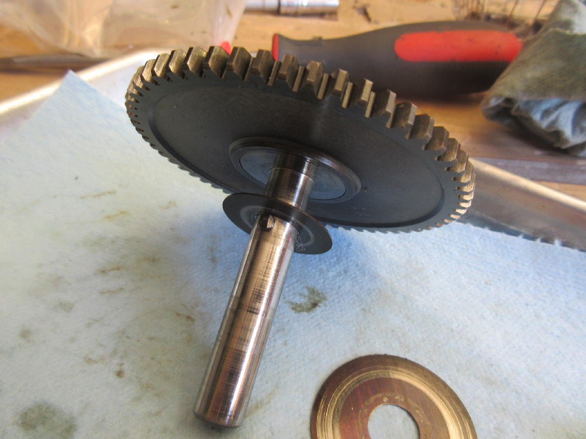
I referred to it as the “pump driven gear” above, in the context of its relationship to the driving gear on the crankshaft, but for the rest of this discussion I refer to it as the “pump drive gear”, shown here with its thin outside washer.
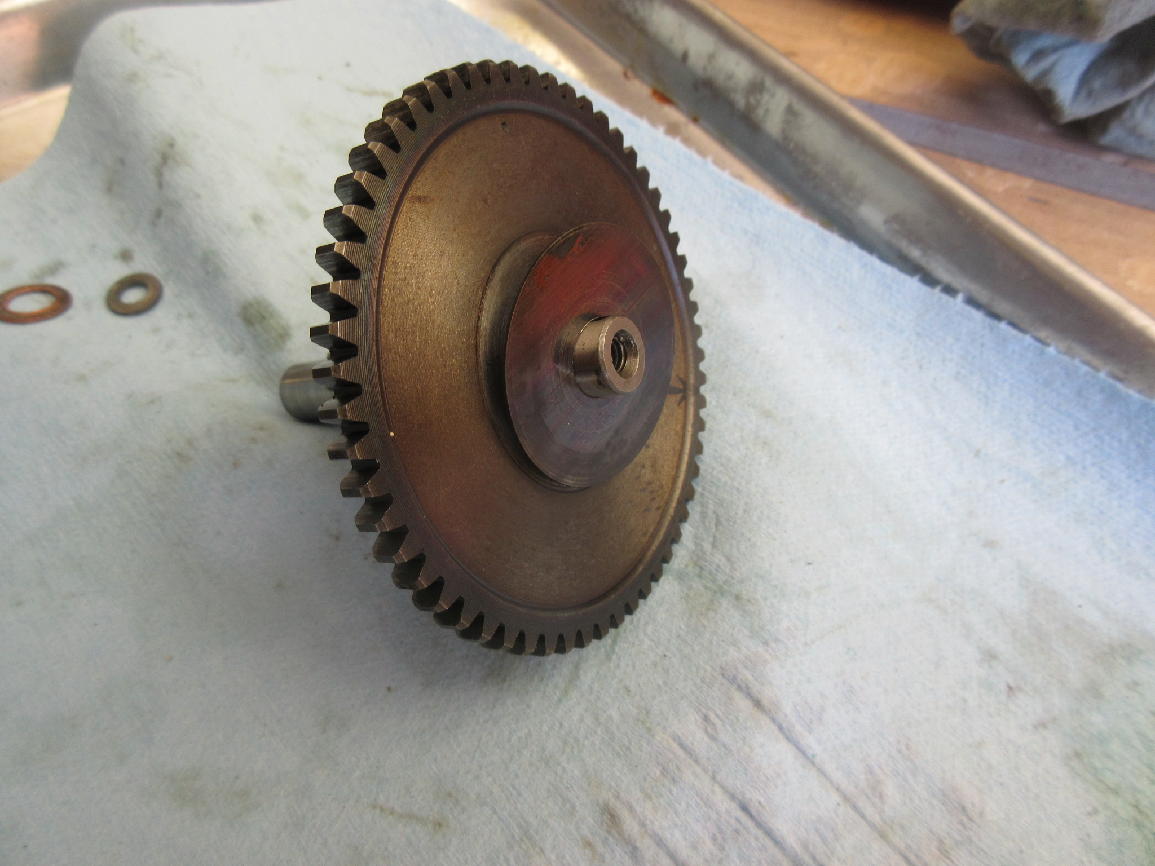
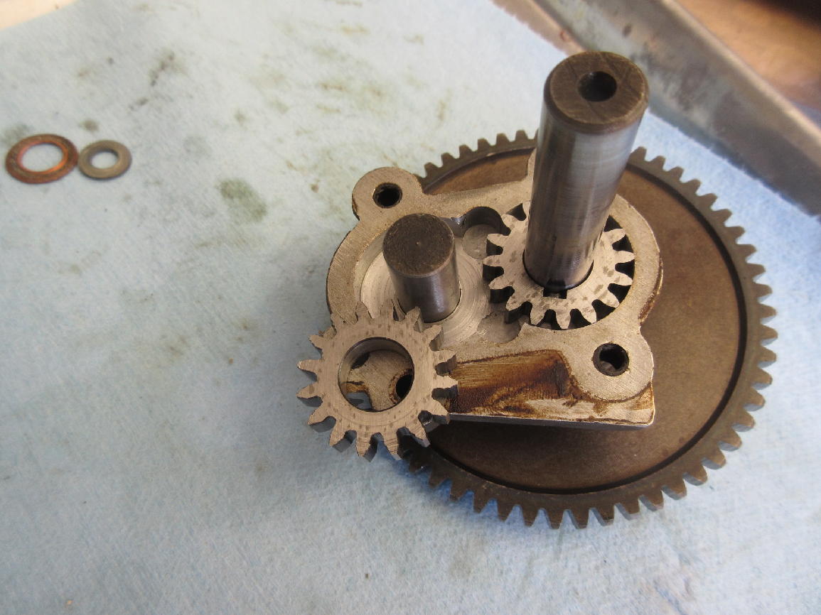
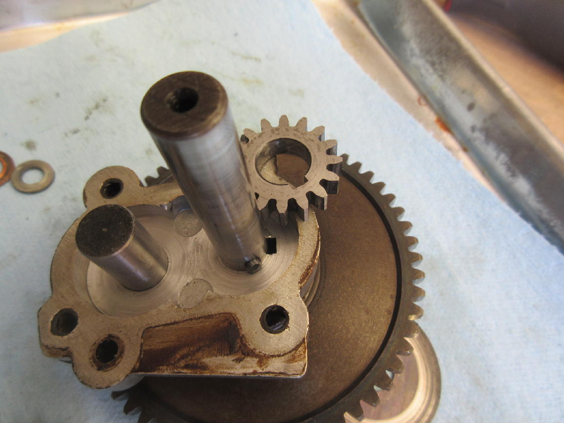
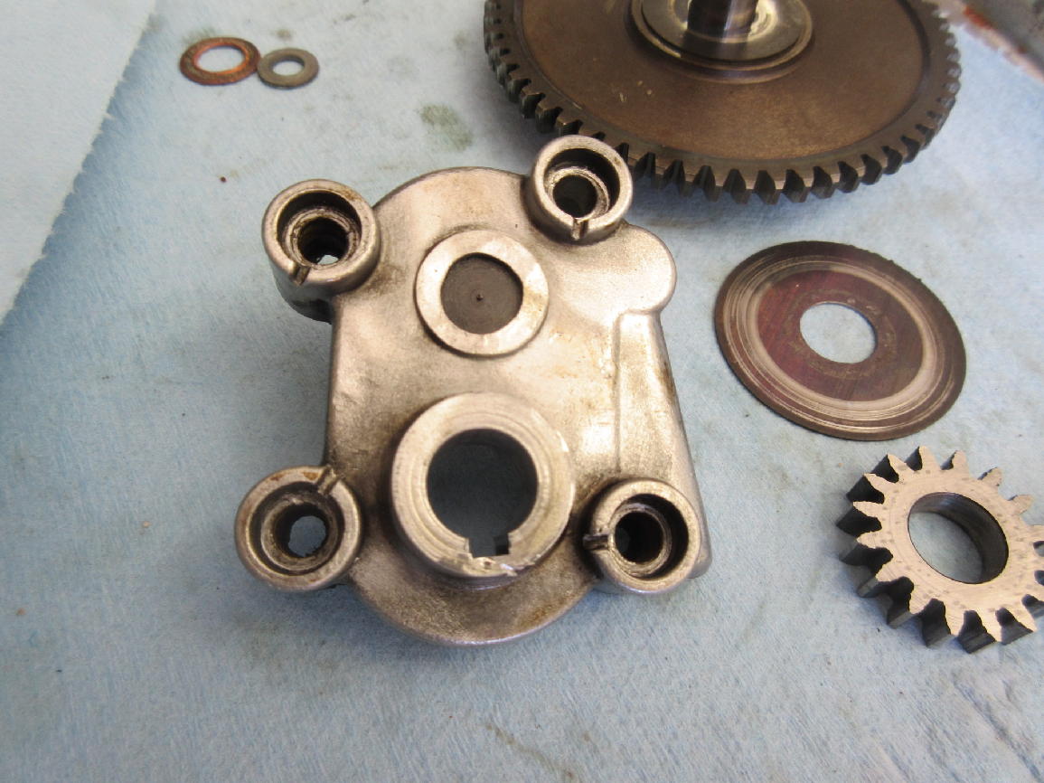
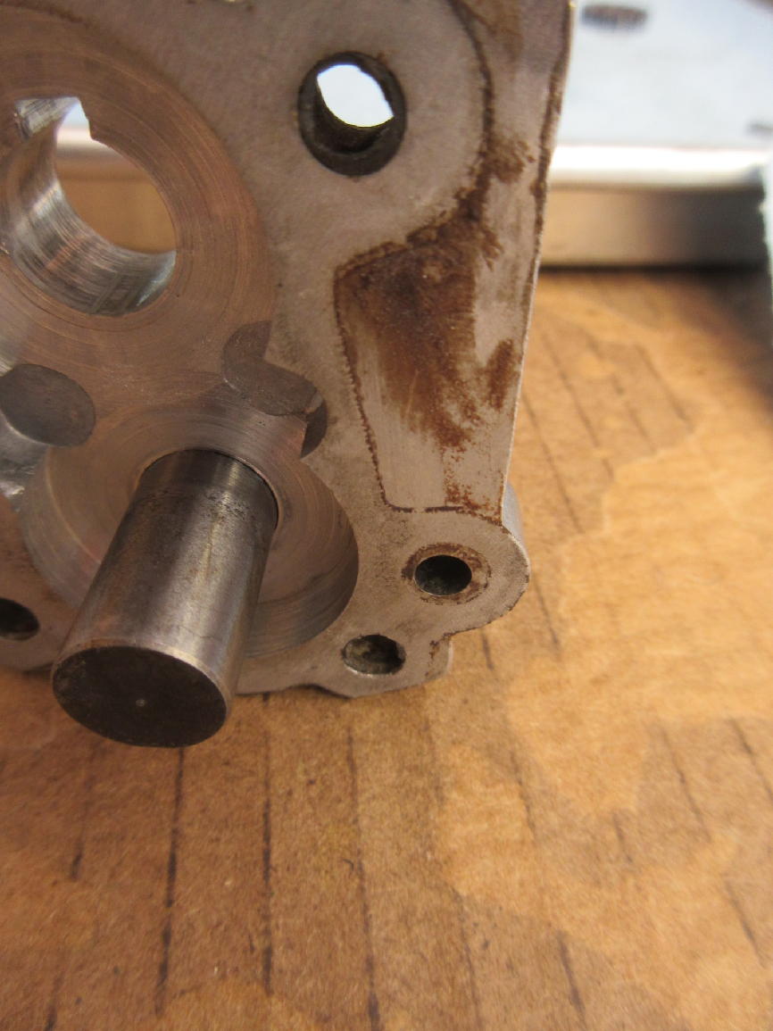
A look at the assembled pump from the backside. The short shaft on the left is fixed and the left-hand pump gear is just an idler. The long shaft of the pump drive gear on the right has a cross-pin that engages the driven pump gear. You can see the keyway in that gear. In the third and fourth photos you can see the slot in the pump housing through which the cross-pin enters.
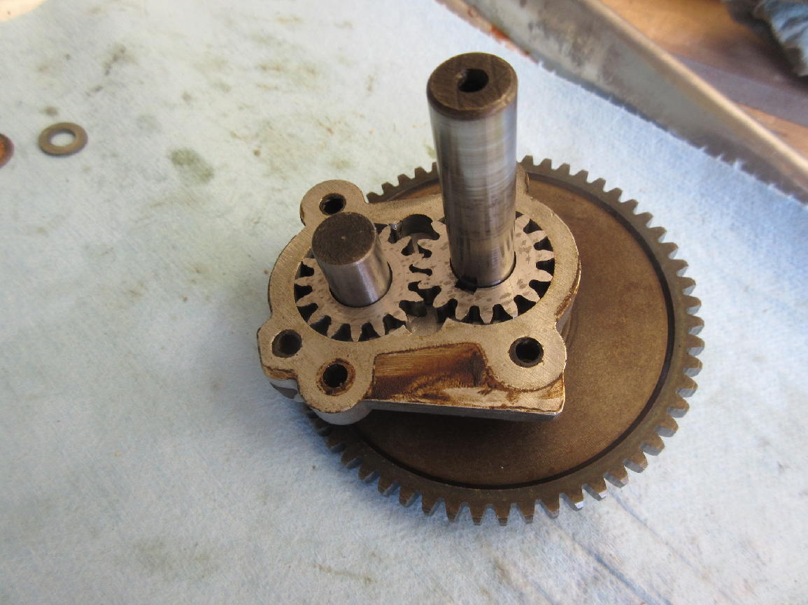
There is another thin washer between the pump drive gear and the pump body.
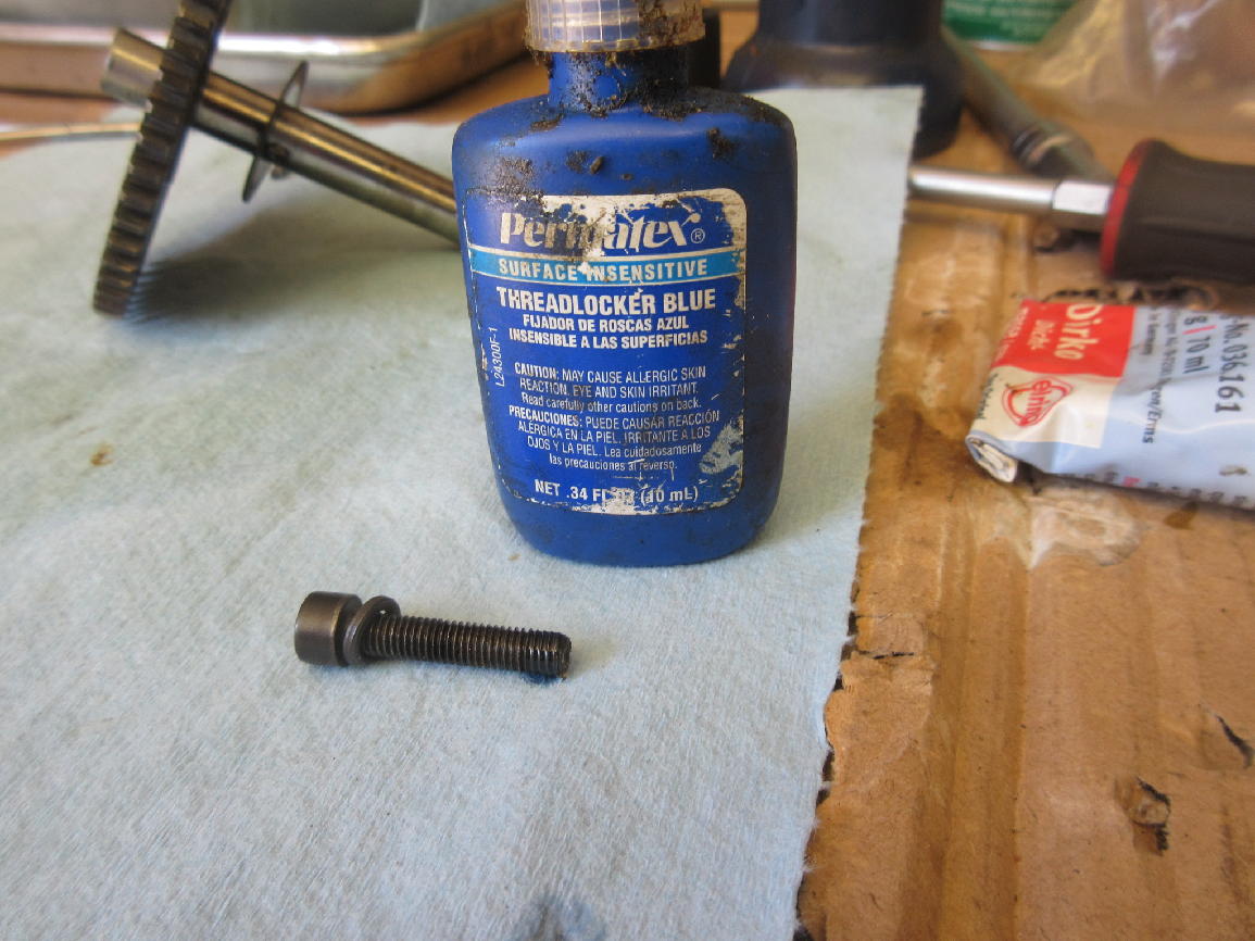
When the factory assembled oil pumps they used slotted screws and staked them through those slots in the towers. At some point those screws have been replaced by socket screws with lock washers.
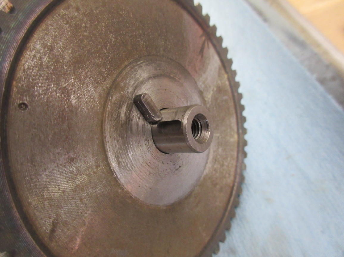
This small key in the shaft outboard of the pump drive gear is what engages the cam of the contact breaker points.
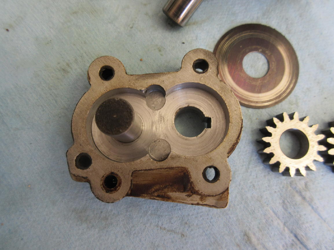
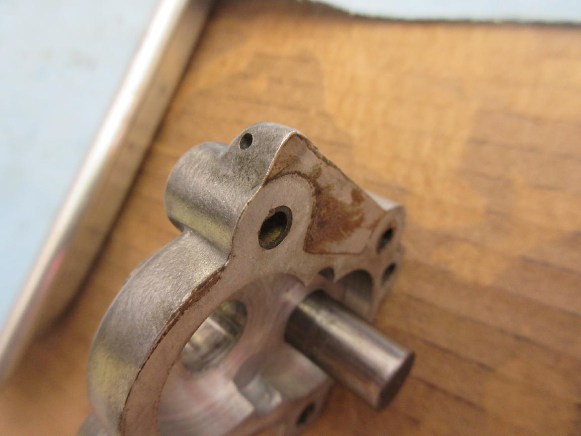
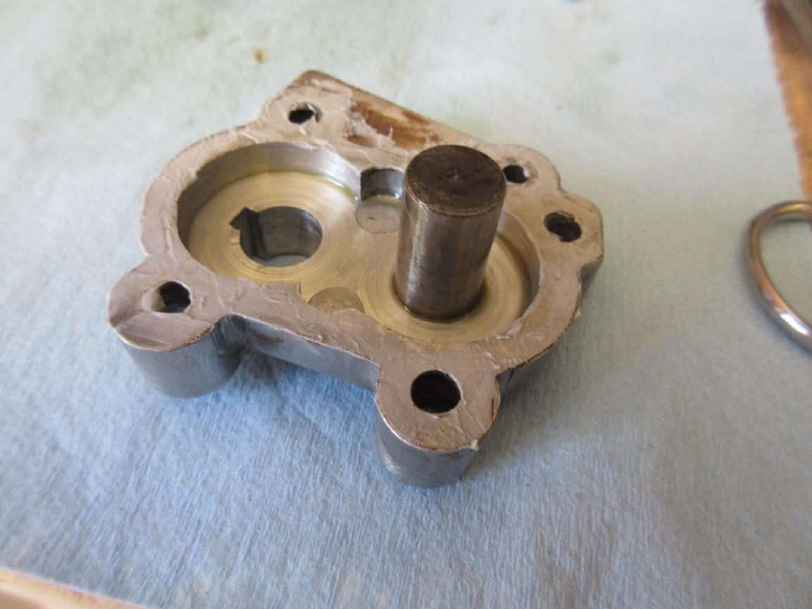
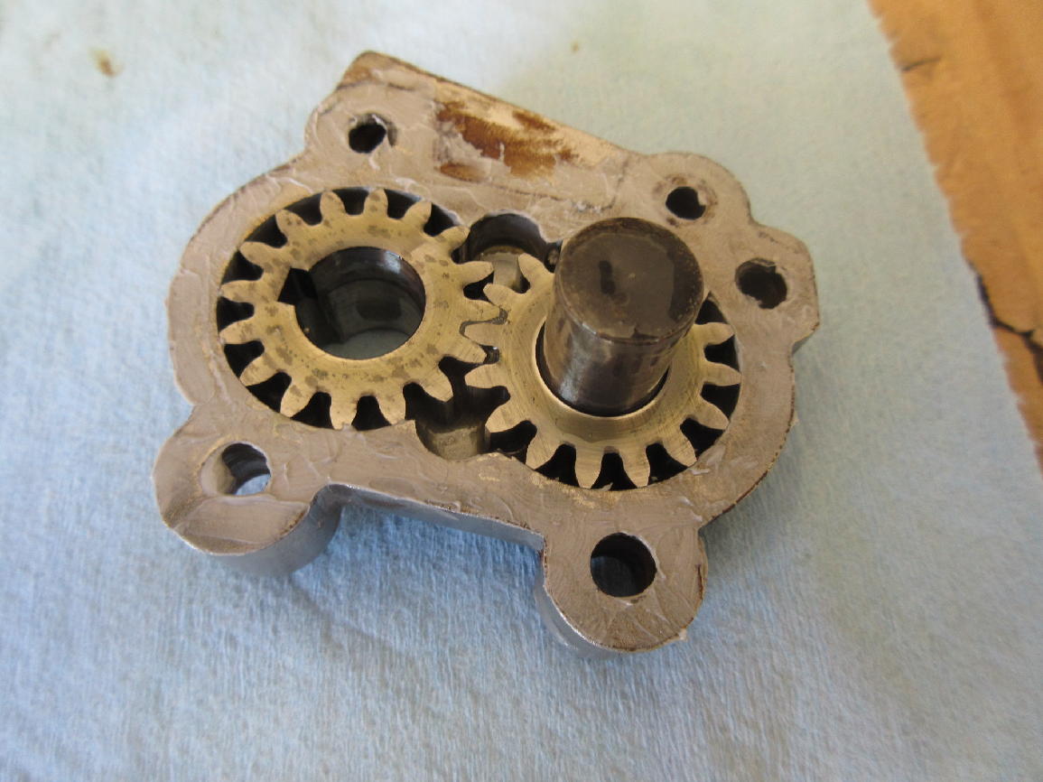
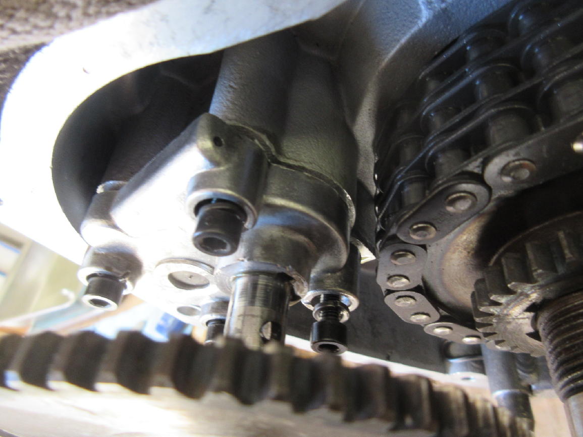
The next three photos show a portion of the oiling system that sprays oil on the primary chain. When the pump is installed this small orifice in the first photo is pointed right at the chain on the front sprocket. In the second photo you can see the feed for that oil spray, picked up from an oil passage in the case (third photo), at about 11 o’clock from the idler shaft bore. The top left securing screw is shifted to make room for it.
The next three photos illustrate my first attempt to assemble the pump and install it on the case. I carefully spread a light coat of Dirko non-hardening sealant (see the page on assembling the bottom end of the engine) on the pump body sealing surfaces, lubed the pump gears with assembly lube, cleaned the screws with spray brake cleaner, and dabbed a little medium-strength loctite on them. I oriented the driven pump gear so its slot lined up with the one in the pump body and attached the pump body to the case without the drive shaft in place. I left the screws just barely snug so I could fiddle the exact alignment of the bore in the case and pump body and then tried to insert the shaft of the pump drive gear, with the cross-pin oriented at 3 o’clock to go through the slot in the pump body. This did not work. I could not wiggle things enough to get the shaft started in the case bore.
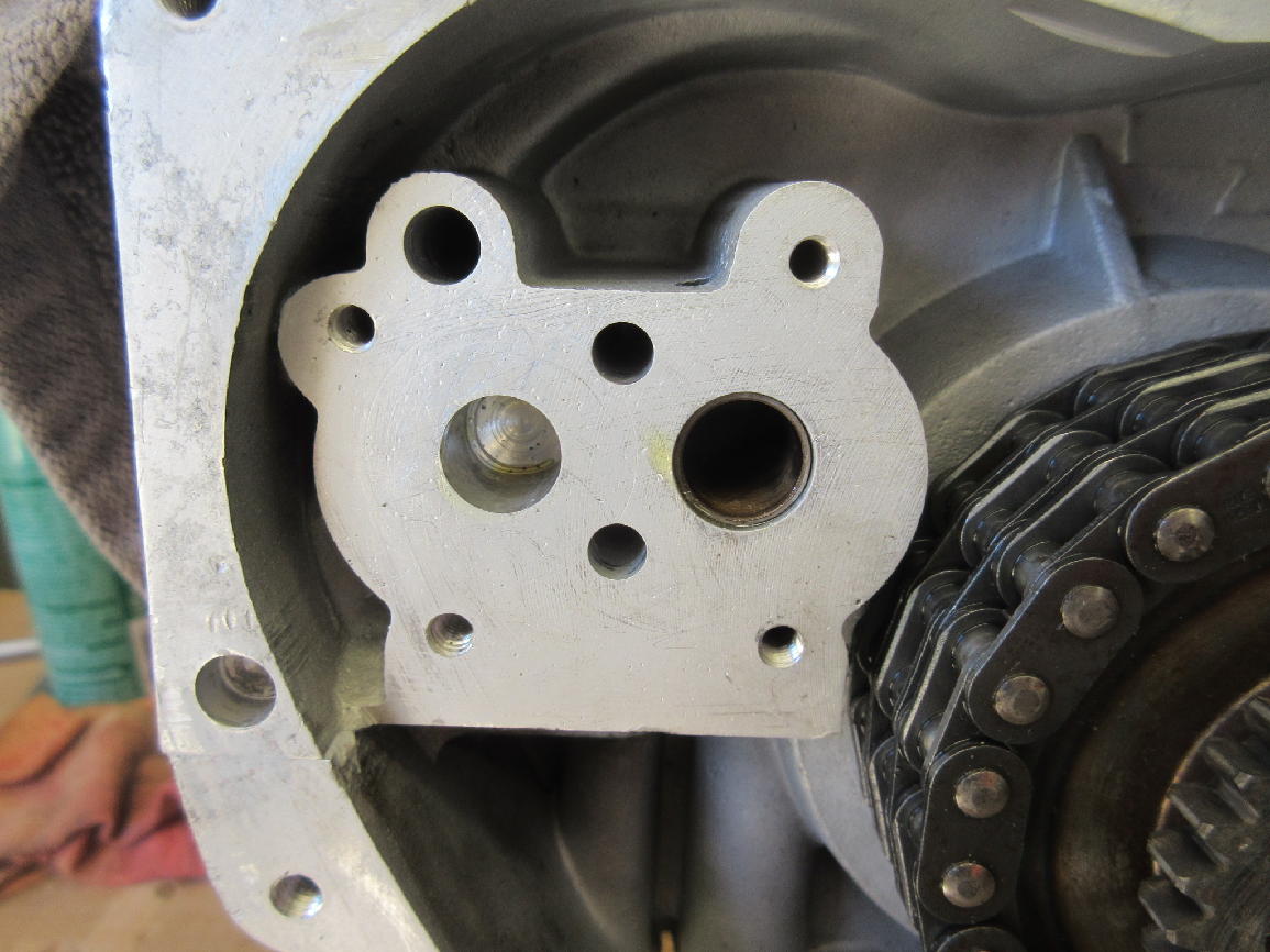
In order to get the initial set-up with the pump drive gear shaft through the driven pump gear and started in the case bore, with the four pump body screws in place, I had to leave the screws just started and the pump body several mm out from the case, as shown in the next photo. You can also see the arrangement of the oil spray hole from the oil pump toward the primary chain.
The next phase of the job required a short-leg allen wrench (4 mm) to slowly draw up the four screws, turning the pump drive gear (and thus the pump gears) a couple times with no binding, then (after making sure it was oriented correctly) making sure I could extract the pump drive shaft and re-insert it and still drive the pump smoothly. This was a slow tedious process.
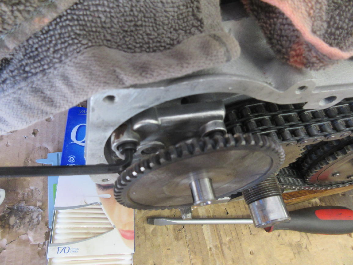
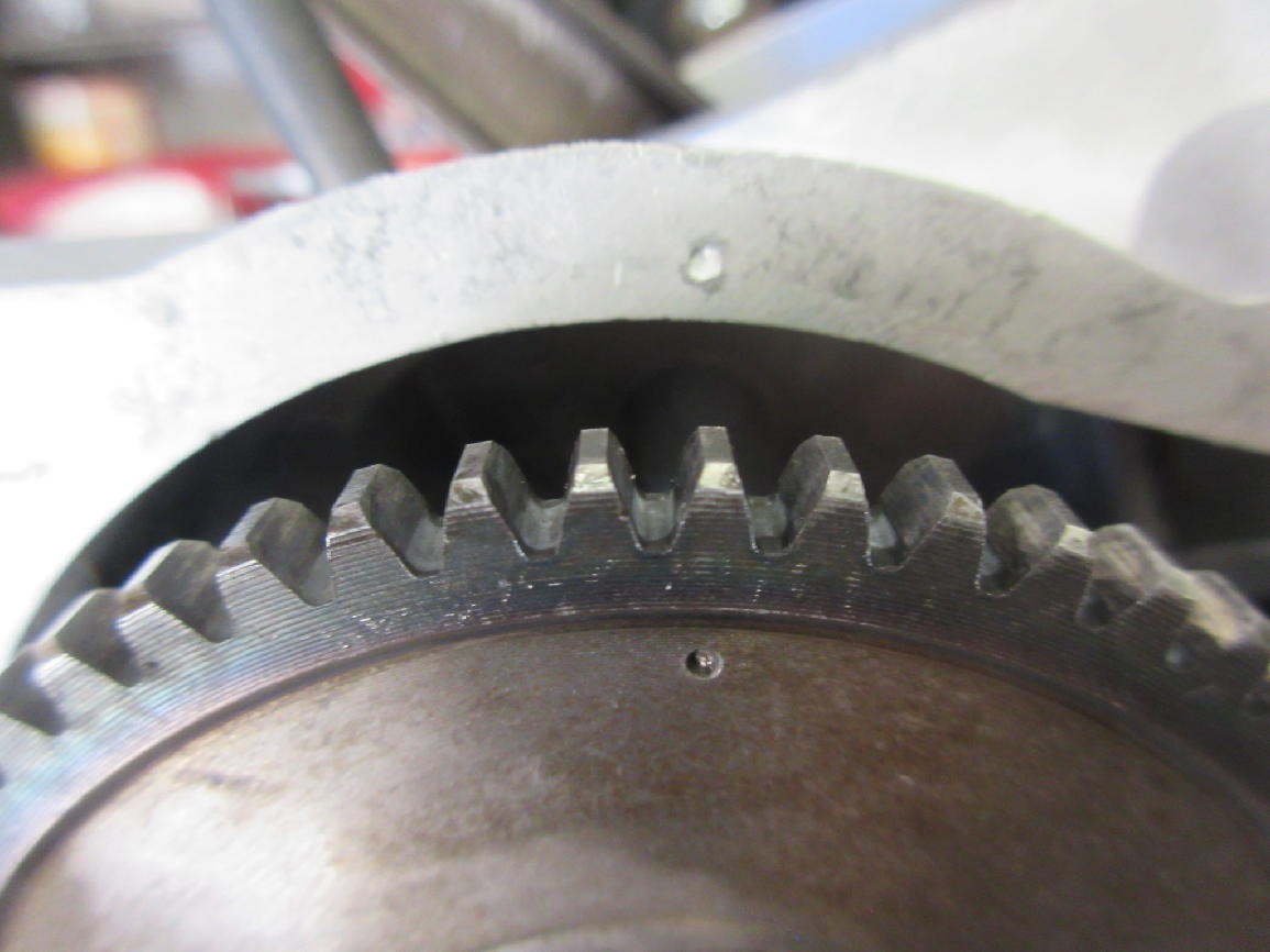
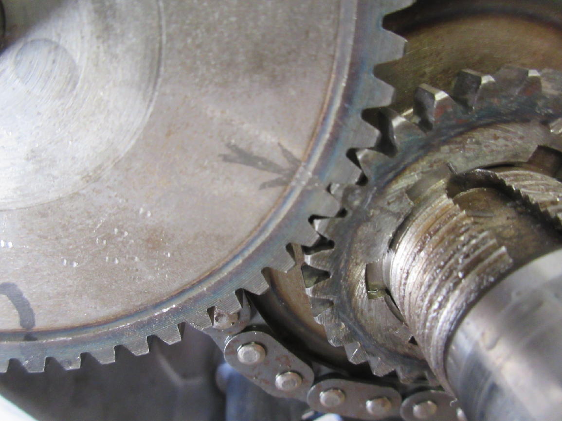
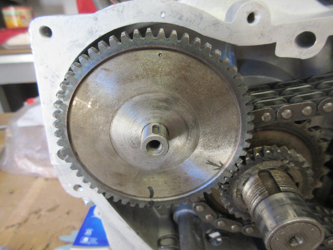
The last three photos illustrate the process of orienting the pump drive gear correctly so the the igniton timing will work. With the engine at TDC there is a dimple near the perimeter of the pump drive gear that will be at twelve o’clock, lining up with a dimple in the edge of the case. There may be marks of some kind on the pump drive gear and the crankshaft gear that will line up in the correct position too. They are useful if you haven’t removed the crankshaft gear, but it can be installed in a half-dozen orientations so it is not fool-proof. In the last photo you can see the mark I made on the pump drive gear (at 6 o’clock in the photo) to show the position of the cross-pin, very helpful during the in- and out-session needed to install the pump.